- The BlueNRG-LPS-HSE-CALIB-RTT is an application example that allows the user to tune the High Speed External (HSE) crystal by adjusting 2 internal capacitors via J-Link RTT.
- This application may be used to find the optimal HSE tune value for your PCB. This value can then be set with the CONFIG_HW_HSE_TUNE preprocessor symbol on your BlueNRG projects.
- The RF frequency is dependent on the HSE. Tuning of the HSE can be done by measuring the HSE clock or RF frequency.
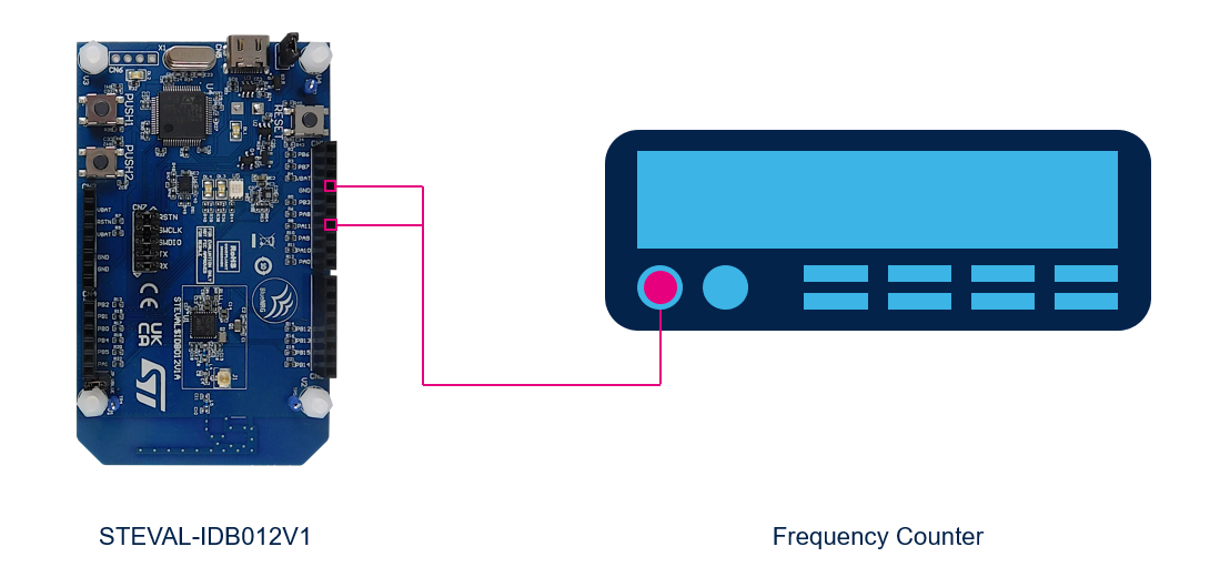
- The HSE clock is output on the Microcontroller Clock Output (MCO) pin: PA11.
- Use a frequency counter to measure the HSE frequency on the MCO pin.
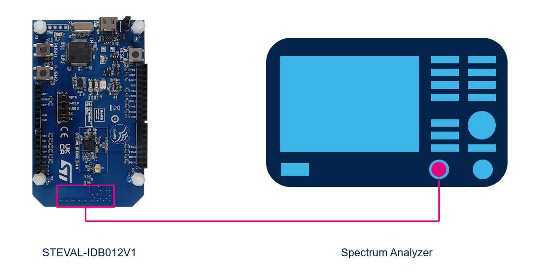
- An RF tone at 2.402 GHz is started automatically at application start and after each change made to the HSE tune value.
- A spectrum analyzer can be used to measure the tone peak, follow section 5.5 in AN5503 to configure the analyzer.
- This application example is based on the RCC_HSE_Calib application for the STM32WB55 found in the X-CUBE-CLKTRIM expansion package.
-
One STEVAL-IDB012V1 (BlueNRG-LPS)
-
One SEGGER J-Link / J-Trace Debug Probe
-
One Frequency Counter (Necessary for HSE Frequency Measurment)
-
One Spectrum Analyzer (Necessary for RF Frequency Measurment)
-
Prebuilt firmware image: BlueNRG-LPS-HSE-CALIB-RTT.hex
-
WISE Studio, IAR EWARM, or Keil MDK-ARM IDE
-
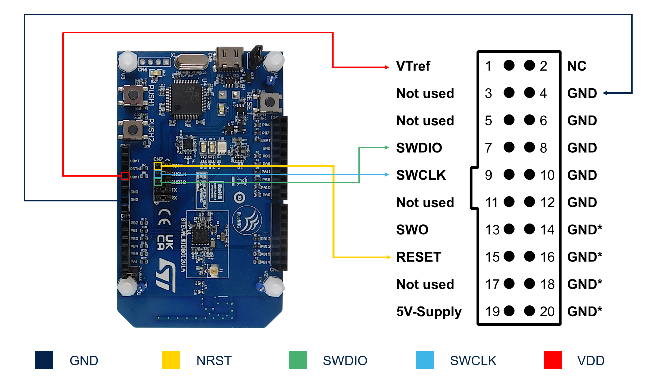
Follow this article to connect the J-Link Debug Probe to the EVAL board.
-
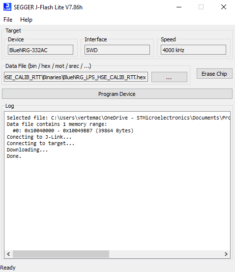
Flash the application firmware on to the board using one of the following options:
a) Use J-Flash LITE included with the J-Link Software Pack to download the hex file on to the board.
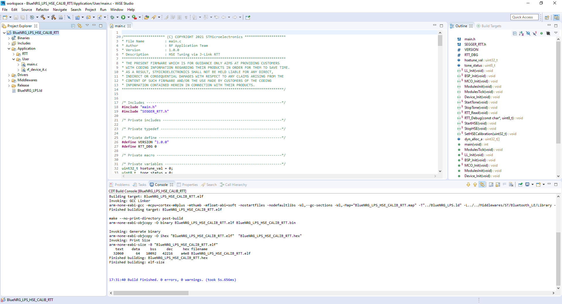
b) Open your preferred IDE and build & run the project to download it on to the board.
-
Connect to one of the following devices to measure the HSE or RF frequency:
a) HSE: Connect the MCO pin (PA11) and the GND pin to a frequency counter.
b) RF: Connect the board to a spectrum analyzer wirelessly using RF antennas.
Note: The antennas should be placed closely together. Follow section 5.5 in AN5503 to configure the analyzer.
-
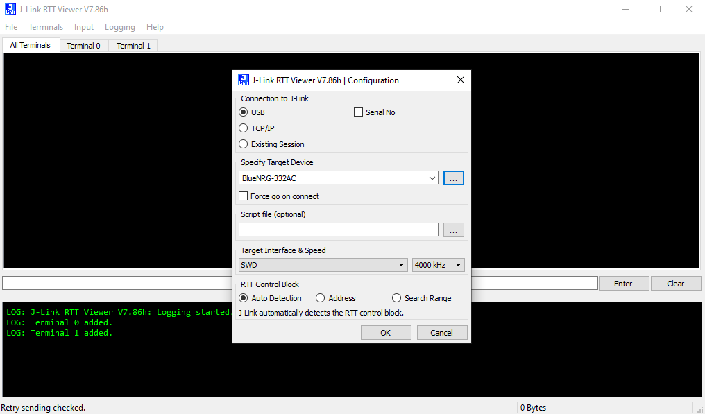
Open RTT Viewer from the J-Link Software Pack and connect to the EVAL board.
-
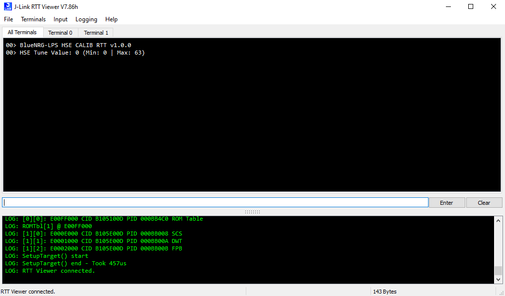
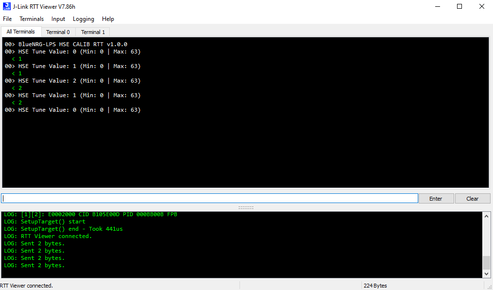
Once the application example has started, you will see an initial message.
Note: You may need to press the RESET button to start the application example.
-
Send '1' or '2' via J-Link RTT to change the HSE tune value (0 - 63).
a) '1': increases the HSE tune value.
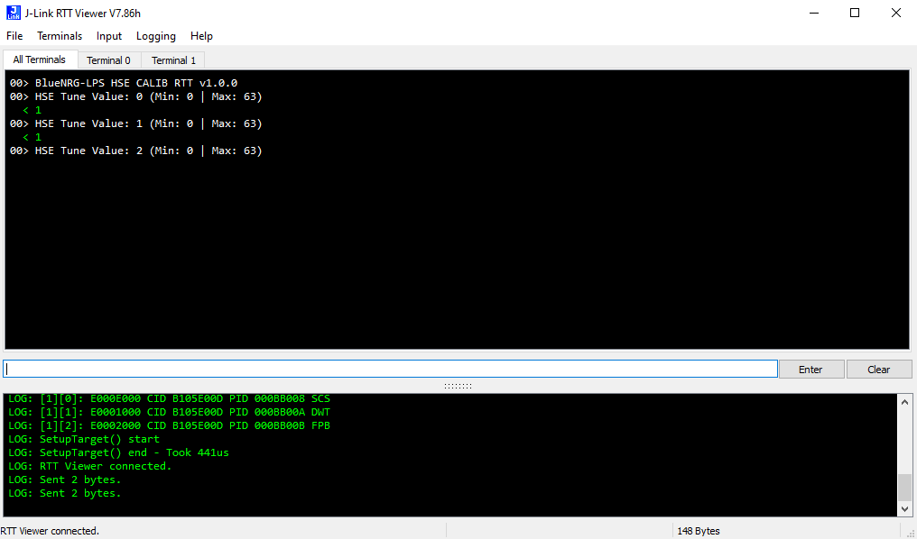
b) '2': decreases the HSE tune value.
-
Tune the HSE until you see the following HSE or RF frequency measurements.
a) HSE Frequency: 32 MHz
b) RF Frequency: 2.402 GHz
-
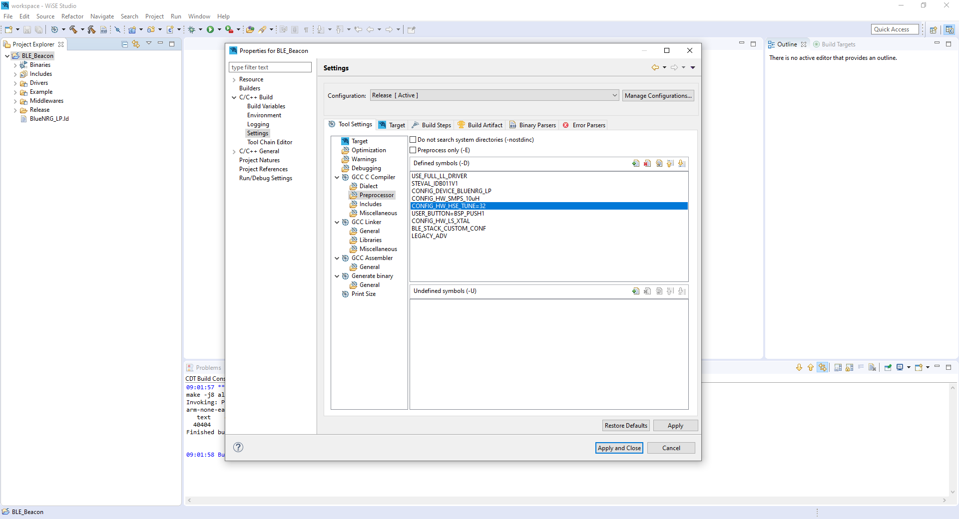
Take note of the optimal HSE tune value and set it using the CONFIG_HW_HSE_TUNE preprocessor symbol on your BlueNRG projects.
Note: The default CONFIG_HW_HSE_TUNE value is set to 32 for BlueNRG examples.


Caution : Issues and the pull-requests are not supported to submit problems or suggestions related to the software delivered in this repository. The BlueNRG-LPS-HSE-CALIB-RTT example is being delivered as-is, and not necessarily supported by ST.
For any other question related to the product, the hardware performance or characteristics, the tools, the environment, you can submit it to the ST Community on the STM32 MCUs related page.