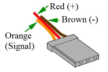
Servo motors are good application area of embedded industry. Robotic, Automotive and industrial machine controlling operations are good samples for applications. Normally, motors are using just “voltage in” and GND pins. But in the servo’s, We have one extra pin that called as signal input and represented by yellow in wiring diagrams. This signal must be PWM. PWM is pulse width modulation. Average voltage feeds load that is controlled motor. In the next chapters, we will use timers and a little calculations.
Firstly, we should setup threads like every project. General purpose timer, pinout and buttons will be generated by SSP configuration panel.
S5 and S4 buttons are defined as IRQ10-IRQ11 in the datasheet.
We can clearly selected pins are true from “port capabilities” section. We need to go back thread windows for extra operation. Pins are interrupt so we should set call-back function and channels. I choose different channel and call-back. Next step timer and pinout configuration.
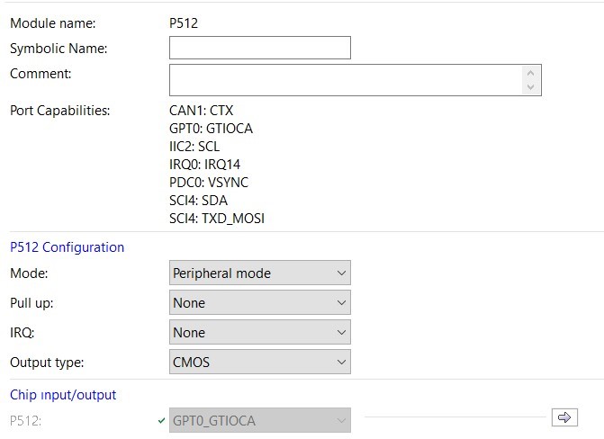
GPT0 has been selected and this timer supports P512 and P511 pinouts. P512 peripheral mode and GPT0 is clear from figure shown below.
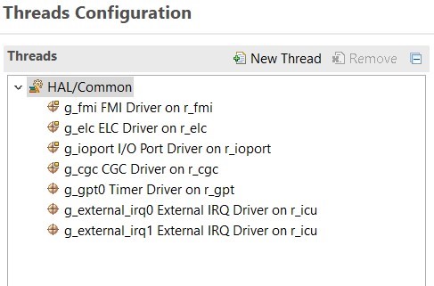
After all this operations thread must be look like figure shown below.
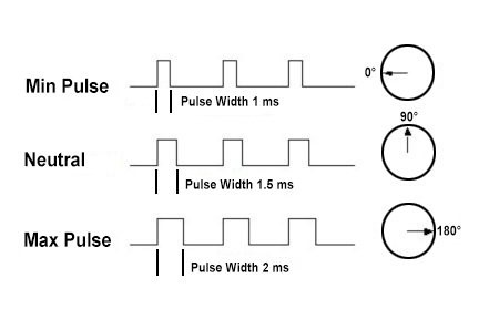
Servo motors are operated 50 Hz PWM signal. Rotation angle depends only between 1ms and 2ms PWM signal at 50 hertz. 50 Hz is 20ms. Min and max operation rates are %5 and %10
That means we should set our timer on 50 Hz period and 5-10% duty cycles.
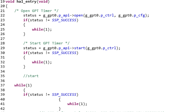
Timer opened and started between line 21 and 34.
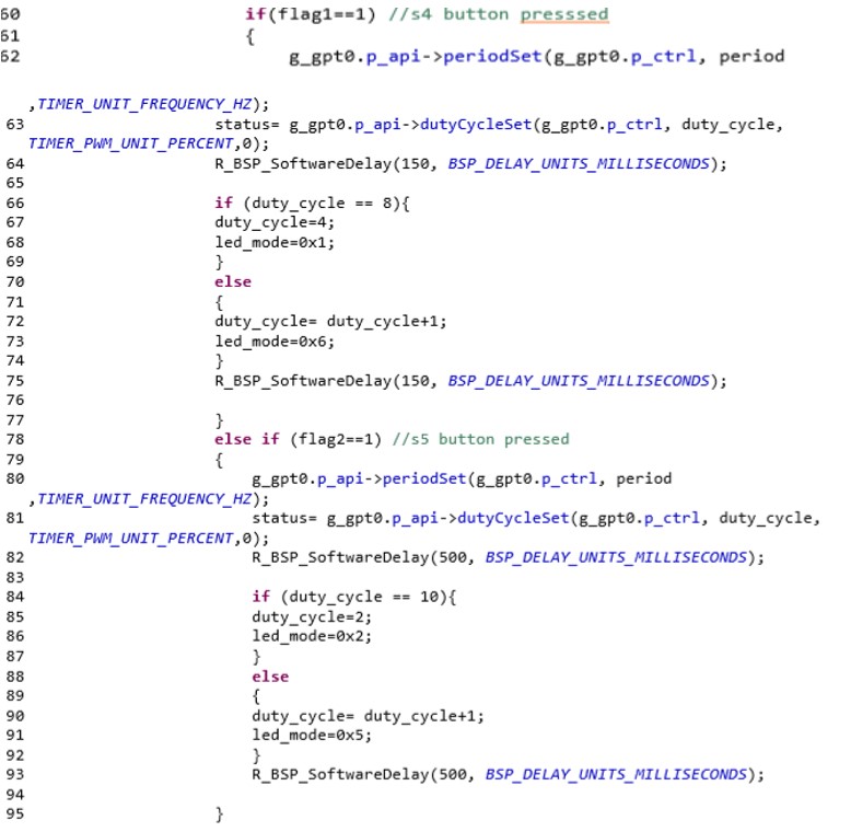
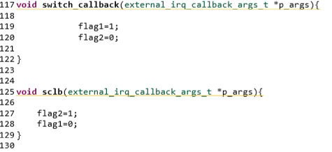
S4 and S5 button conditions are defined. Flag1 and Flag2 are interrupt flags. Last step is call-back functions.
Initial parameters
Led_mode pre-processor is represent user LED control register. If you define hex number to this pointer, LED output will be high. 1-green, 2-red, 4-yellow LED value. But you can use 1-8 for different combinations.
I used PWM, BLINKY and basic embedded knowledge in this project. It helped my embedded software development knowledge RENESAS Synergy Software Package. Step motor works well and led’s are blinking. In this course labs, We analysed PWM, TIMER, IRQBUTTON, and LED labs. I combined all of them into one project.
-Renesas undergraduate course lab sheets
-https://www.jameco.com/jameco/workshop/howitworks/how-servo-motors-work.html
-Suleyman INCI’s previous works


