Self-Driving Car Engineer Nanodegree Program
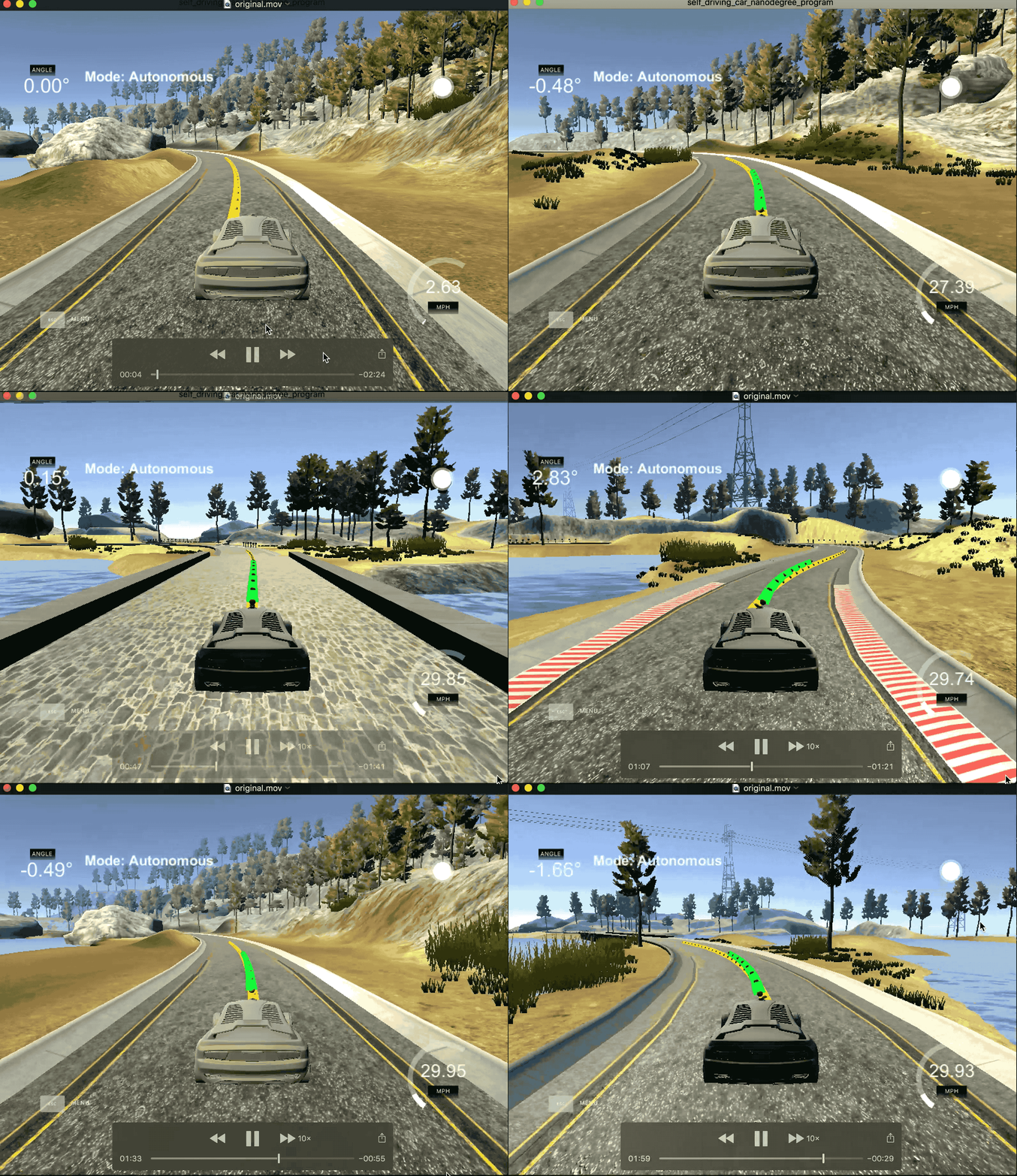
The goal of this project is to build a model predictive controller to maneuver a car in the simulator. MPC estimates the path for the next few steps based on the current system state to arrive at the parameters for actuating the vehicle. The process is continued on every single step to predict the path for the upcoming few steps based on the new system state.
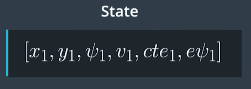
The state of the system is defined by the position of the car x and y, heading of the car psi, velocity v, cross-track error cte and orientation error epsi. The system has two actuators steering angle (wheel) delta and accelerator (throttle) a. The model should consider the current system state, estimate the expected system state in dt and provide controls to the actuators.
The system model can be mathematically defined as shown in the below image, where Lf is the distance between the center of gravity (CoG) and the front axle of the vehicle which is a constant for a given vehicle. The model best fits an ideal world, where the true interaction between the tries and road such as slipping, skidding, air-drag etc are ignored.
Steering angle and throttle are the two actuators that will be controlled by the model. The actuators are constrained with practical limits, eg. the steering angle cannot be any more than 25 degrees in either direction and the maximum acceleration can only be in the range of -1 and +1. Negative value indicating brake and positive indicating throttle.
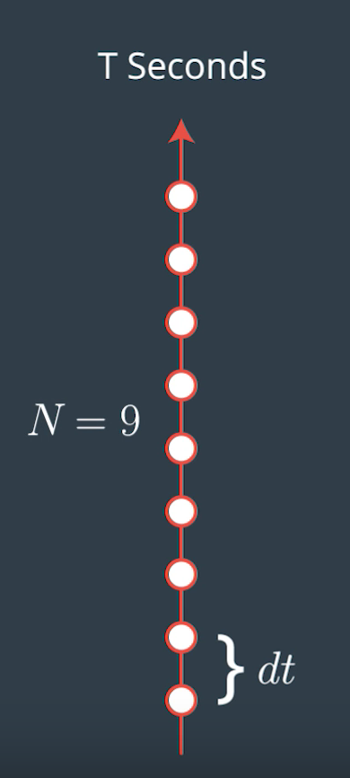
The model predicts the next N steps in the target trajectory based on the current system state. The number of future steps and the time difference between the steps are critical hyperparameters that needs to be optimized. In a realistic world, the actuators imposes an inherent delay in causing the expected result in the system, the simulator here accounts for this delay by introducing a 100ms latency to actuate the final system parameters. Therefore, before optimizing the cost function this predicted trajectory is updated to account for this latency.
The below values for no. of steps and step duration seems to work very well for the model.
size_t N = 10;
double dt = 0.1;
A 3rd order polynomial is fit over the projected waypoints, this path will be optimized for cte & epsi using the below cost function.
To ensure smooth transition of actuators values the gap between the actuator values for consecutive points are heavily penalized during cost function optimization to avoid drastic swerve motion in the vehicle. For both the actuators upper and lower bound values are set to practical limits. In case of steering angle the maximum limits are set to ± 0.43632/Lf, where Lf is distance between center of gravity and front axle. The resulting actuator vector is applied only on the very first step and the process is continued after every single step to continuously project/predict the target path.
- Clone this repo.
- Run
brew install mumps - Run
brew install ipopt - Make a build directory:
mkdir build && cd build - Compile:
cmake .. && make - Run it:
./mpc.


