Control and read out directly the TCD1304AP CCD linear array (http://oceanoptics.com/wp-content/uploads/Toshiba-TCD1304AP-CCD-array.pdf) with a teensy2++ (https://www.pjrc.com/store/teensypp.html). It should work (with probably a bit of configuration) with an arduino Mega2560, but other arduino boards have too little RAM to read all pixels (the TCD1304AP has 3648 pixels, so to read all pixels at least 4k of memory is needed).
TCD1304AP_teensy2pp is distrubuted under GPL v3 (https://www.gnu.org/licenses/gpl-3.0.txt).
example of a reading illuminated by a LED:

example of a reading illuminated by a LED with the shadow of a 3.5 mm bit:

- Installation ==============
- Download and install the arduino software 1.6.9 (https://www.arduino.cc/en/Main/OldSoftwareReleases)
- Download and install teensyduino (https://www.pjrc.com/teensy/td_download.html)
- Download TCD1304AP_teensy2pp, open the TCD1304ap.ino file with the arduino software, compile and upload the sketch to your teensy2++.
- Wiring ==============
| Teensy2++ | | TCD1304A | | Other
OC2A/PB4 pin ---> PhiM
OC3A/PC6 pin ---> ICG
OC1A/PB5 pin ---> SH
ADC0/PF0 pin <--- OS
PC0 pin ----------------------------------> LED (in series with an appropriate resistor)
- Description/ Usage ==============
This program has been written to use the TCD1304AP as a filament width sensor (a bit like http://www.thingiverse.com/thing:454584). However as the TCD1304AP sensor is cheap (3.5$ on ebay) and no additional component are needed to interface it, it makes the TCD1304AP solution very competitive.
The TCD1304AP sensor is driven without using the electric shutter function, so the illumination control is done by choosing the duration the LED is switched on during the acquisition.
Once the sketch is running on your teensy2++ and the wiring is done, just plug the USB cable to your computer and run "python read_pixel.py" to see live the readings of the TCD304AP. As the TCD1304AP is very sensitive, it must be put with the LED in a totally opaque enclosure, otherwise you will only read saturated pixels.
As you can see in chapter 4, the teensy2++ is really pushed to its limits:
- timer0 is used to control the time the LED is on (typicaly few ms).
- timer1 is used for SH generation (SH freq = 4x the pixel rate).
- timer2 is used to trigger ADC and to generate the interupts to read the pixels values.
- ADC can be run between 615 kSample/s (prescaler=2) and 77kSample/s (prescaler=16) whereas the datasheet recomands 15kSample/s (prescaler=64) to get the maximum resolution.
- during acquisition, almost 100% of the CPU cycles are spent in the interupt routine reading the pixels values.
- Configuration ==============
Most of the teensy2++ pins used to control the TCD1304AP can easily be changed in tcd1304ap.h (not tested yet, please report if it works):
- to change the pin connected to ICG, change the value of ICG, ICG_HIGH() and ICG_LOW()
- to change the pin connected to SH, change the value of SH
- to change the pin connected to OS, change the value of OS (it must be an ADC pin)
- to change the pin connected to the LED, change the value of LED.
- the pin connected to PhiM cannot be easily changed (it must to be a pin controlled by a timer and the code has to be change in several places)
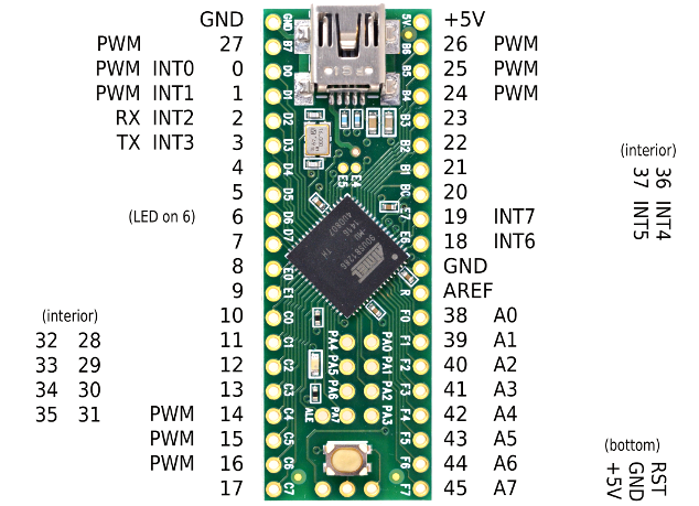
You can refer to the following image to know what value correspond to what pin.
There are few parameters you may want to set in the TCD1304ap.ino file (the values there works great for me):
- The pixel rate (in MHz), as 1st argument of the tcd1304ap::init() function in setup()
- The ADC prescaler value (any power of 2 between 2 and 128), as 2nd argument of the tcd1304ap::init() function in setup()
- The duration the LED is switched on (in us), as the only argument of tcd1304ap::readout_and_capture() in loop()
Before you change these values, you should know:
- The minimum pixel rate in the TCD1304AP specification is 0.2MHz. However, I was not able to run at this frequency, as it let too little time to make the ADC conversion and sore the reading in memory.
- The mimimum pixel rate that my TCD1304AP supports is 0.067Mhz.
- The maximum pixel rate I could get without missing any pixel was 0.07-0.08MHz, above that, for some pixles, the ADC conversion is not finished by the time an other pixel is sent by the TCD1304AP. These pixels are sent to the PC as having a value of -1.
- The maximum pixel rate I could get without having my pixel readings unpredictably shifted was 0.133MHz. Above that, the readings are basically useless as you cannot be sure anymore of which pixels gave you the reading.
- Decreasing the ADC prescaler makes the ADC run faster, so you can go up a bit in pixel rate, but the resolution of the ADC decreases as well.
- TODO ==============
I plan to make:
- a function to find automatically the best duration for the LED to be switch on (best contrast but no saturation).
- a function to analyze the CCD sensor readings and calculate the width of the object between the LED and the CCD sensor.
- a function which send the width of the object using one of the teensy DAC output (MARLIN compatibility )
- a python function to calibrate this width measurement using f.e. bits with known diameters.