The ADI 3DToF Image Stitching is a ROS (Robot Operating System) package for stitching depth images from multiple Time-Of-Flight sensors like ADI’s ADTF3175D ToF sensor. This node subscribes to captured Depth and IR images from multiple ADI 3DToF ADTF31xx nodes, stitches them to create a single expanded field of view and publishes the stitched Depth, IR and PointCloud as ROS topics. The node publishes Stitched Depth and IR Images at 2048x512 (16 bits per image) resolution @ 10FPS in realtime mode on AAEON BOXER-8250AI, while stitching inputs from 4 different EVAL-ADTF3175D Sensor Modules and giving an expanded FOV of 278 Degrees. Along with the Stitched Depth and IR frames, the Stitched Point Cloud is also published at 10FPS.
- Supported Time-of-flight boards: ADTF3175D
- Supported ROS and OS distro: Noetic (Ubuntu 20.04)
- Supported platform: armV8 64-bit (arm64) and Intel Core x86_64(amd64) processors(Core i3, Core i5 and Core i7)
For the tested setup with GPU inference support, the following are used:
- 4 x EVAL-ADTF3175D Modules
- 1 x AAEON BOXER-8250AI
- 1 x External 12V power supply
- 4 x Usb type-c to type-A cables - with 5gbps data speed support
Minimum requirements for a test setup on host laptop/computer CPU:
- 2 x EVAL-ADTF3175D Modules
- Host laptop with intel i5 or higher cpu running Ubuntu-20.04LTS or WSL2 with Ubuntu-20.04
- 2 x USB type-c to type-A cables - with 5gbps data speed support
- USB power hub
📝 _Note: Refer the User Guide to ensure the eval module has adequate power supply during operation.
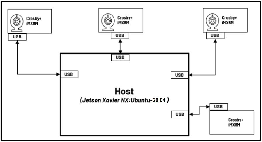
The image below shows the connection diagram of the setup (with labels):
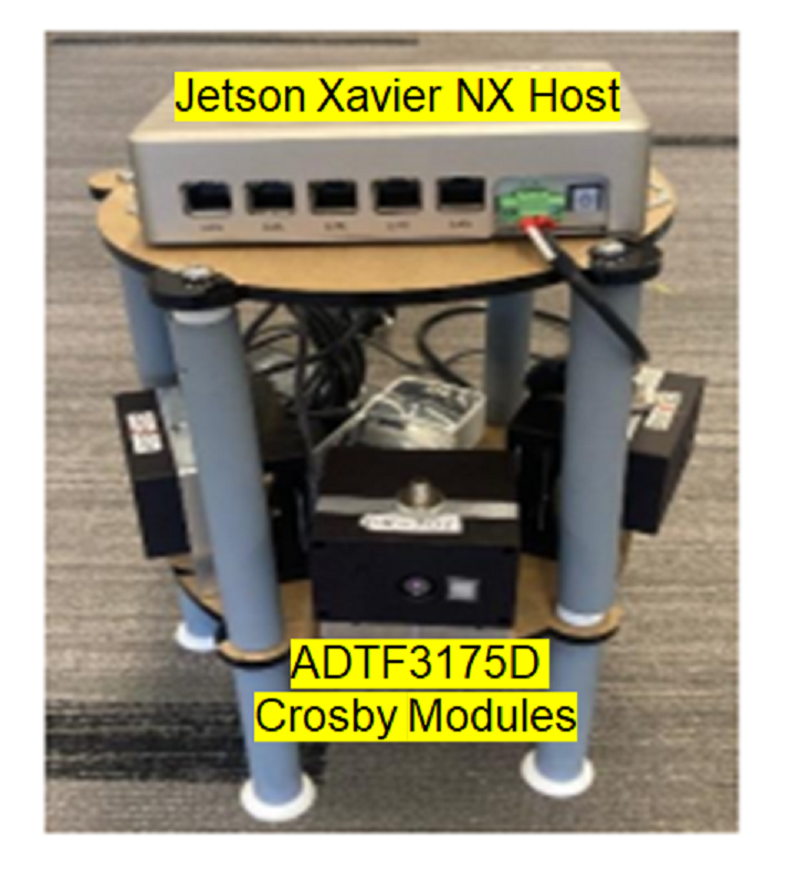
The image below shows the actual setup used (for reference):
Follow the below mentioned steps to get the hardware setup ready:
- Setup the ToF devices with adi_3dtof_adtf31xx_sensor node following the steps mentioned in the repository.
- Ensure all devices are running at
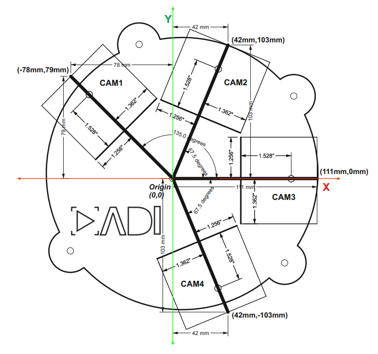
10fpsby following these steps. - Position the cameras properly as per the dimentions shown in the below Diagram.
📝 Notes:
- Please contact the
Maintainersto get the CAD design for the baseplate setup shown above.
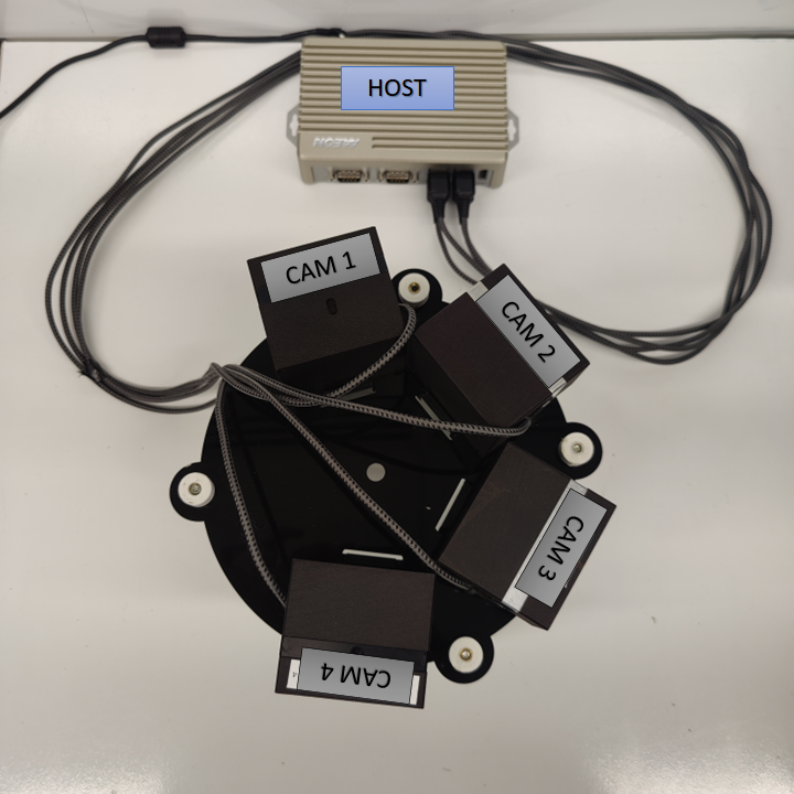
- Finally, connect the devices to the host(Linux PC or AAEON BOXER-8250AI) using usb cables as shown below.
Assumptions before building this package:
- Linux System or WSL2(Only Simulation Mode supported) running Ubuntu 20.04LTS
- ROS Noetic: If not installed, follow these steps.
- Setup catkin workspace (with workspace folder named as "catkin_ws"). If not done, follow these steps.
- System Date/Time is updated: Make sure the Date/Time is set properly before compiling and running the application. Connecting to a WiFi network would make sure the Date/Time is set properly.
- NTP server is setup for device Synchronization. If not, please refer this Link to setup NTP server on Host.
Software Requirements for Running on AAEON BOXER-8250AI :
- Nvidia Jetpack OS 5.0.2 .
- CUDA 11.4. It comes preinstalled with Jetpack OS. If not, follow these steps.
-
Clone the repo and checkout the corect release branch/ tag into catkin workspace directory
$ cd ~/catkin_ws/src
$ git clone https://github.com/analogdevicesinc/adi_3dtof_image_stitching.git -b v1.1.0
Do proper exports first:
$ source /opt/ros/<ROS version>/setup.bashWhere:
- "ROS version" is the user's actual ROS version
Then:
For setup with GPU inference support using CUDA:
$ cd ~/catkin_ws/
$ catkin_make clean
$ catkin_make -DENABLE_GPU=true -DCMAKE_BUILD_TYPE=Release -j2
$ source devel/setup.bash
For setup with CPU inference support using openMP:
$ cd ~/catkin_ws/
$ catkin_make clean
$ catkin_make -DCMAKE_BUILD_TYPE=Release -j2
$ source devel/setup.bashThe default IP address of the sensor is set to 10.42.0.1. It is essential that each sensor has its own IP to avoid conflicts. To do so, ssh into the sensor with the credentials:
Username: analog
Password: analog
- Update the "Address" field in
/etc/systemd/network/20-wired-usb0.networkfile. - Update the
ROS_MASTER_URIandROS_IPvalues in~/.bashrc. For example,
$ export ROS_MASTER_URI=http://10.43.0.100:11311
$ export ROS_IP=10.43.0.1- Update the server address in
/etc/ntp.conf(server 10.4x.0.100 iburst) - Reboot the device and login with the new ip
The sensor modules may be missing the required launch files that designate the transforms for the sensors in 3D space, which is essential the image stitching algorithm to work appropriately. to do so, we transfer the appropriate launch file, refer to the table below, to transfer to the corresponding sensor. Refer to the CAD diagram to determine the location and camera tag.
| Camera | Launch file |
|---|---|
| cam1 | adi_3dtof_adtf31xx_cam1.launch |
| cam2 | adi_3dtof_adtf31xx_cam2.launch |
| cam3 | adi_3dtof_adtf31xx_cam3.launch |
| cam4 | adi_3dtof_adtf31xx_cam4.launch |
To transfer the launch file
$ cd ~/catkin_ws/src/adi_3dtof_image_stitching/launch
$ scp adi_3dtof_adtf31xx_cam1.launch analog@10.42.0.1:/home/analog/catkin_ws/adi_3dtof_adtf31xx/launch📝 Note: For those with <cam_name> in the topic names, these are ideally the names assigned for EVAL-ADTF3175D camera modules. For example, if there are 2 cameras used, with the names as cam1 and cam2 ,there should be two subscribed topics for depth_image, specifically /tmc_info_0 for camra 1 and then /tmc_info_1 for camera 2.
These are the default topic names, topic names can be modified as a ROS parameter.
-
/adi_3dtof_image_stitching/depth_image
- Stitched 16-bit output Depth image of size 2048X512
-
/adi_3dtof_image_stitching/ir_image
- Stitched 16-bit output IR image of size 2048X512
-
/adi_3dtof_image_stitching/point_cloud
- Point cloud 3D model of the stitched environment of size 2048X512X3
- /<cam_name>/ir_image
- 512X512 16-bit IR image from sensor node
- /<cam_name>/depth_image
- 512X512 16-bit Depth image from sensor node
- /<cam_name>/camera_info
- Camera information of the sensor
📝 Notes:
- If any of these parameters are not set/declared, default values will be used.
- param_camera_prefixes (vector, default: ["cam1","cam2","cam3","cam4"])
- This list indicates the camera names of sensors connected for image stitching.
- we support 2 sensors in minimum and 4 sensors at maximum for a horizontal setup at the moment.
- The camera names must match the camera name assigned in the adi_3dtof_adtf31xx sensor node for the respective sensors.
- param_camera_link (String, default: "adi_camera_link")
- Name of camera Link
- image_transport (String, default: "compressedDepth")
- Indicates if Depth compression is enabled for the inputs comming in from the adi_3dtof_adtf31xx sensor nodes
- set this to "raw" if Depth compression is disabled
- param_output_mode (int, default: 0)
- Enables/disables saving of stitched output.
- set this to 1 to enable video output saving.
📝 _Notes:_Enabling video output slows down the speed of image stitching algorithm.
- param_out_file_name (String, default: "stitched_output.avi")
- output location to save stitched output if "param_output_mode" is enabled.
To do a quick test of image Stitching Algorithm, there is a simulation FILEIO setup that you can run. Idea is, 4 adi_3dtof_adtf31xx sensor nodes will run in FILEIO mode on recorded vectors, publising sensor Depth and IR data which will be subscribed and processed by adi_3dtof_image_stitching node:
- adi_3dtof_adtf31xx reads the binary recorded files and publishes depth_image ir_image and camera_info
- The adi_3dtof_image_stitching node subscribes to the incoming data and runs image stitching algorithm on them.
- It then publishes stitched Depth and IR images, along with stitched Point-cloud.
The adi_3dtof_input_video_files folder contains the binary video files which can be obtained by running the get_video.sh script provided by the release file. This folder is to be located in the source folder of your workspace. For example ~/catkin_ws/src.
📝 Notes:
- Running the adi_3dtof_image_stitching node in Simulation mode requires the setup of adi_3dtof_adtf31xx_sensor node to be done before hand.
- It is assumed that both adi_3dtof_image_stitching node and adi_3dtof_adtf31xx node are built in the location "~/catkin_ws/".
- It is also assumed that the demo vectors folder "adi_3dtof_input_video_files" is copied to the location "~/catkin_ws/src/". (please refer the "arg_in_file_name" in the launch files)
To proceed with the test, execute these following command:
| Terminal |
|---|
$cd ~/catkin_ws/ |
When running the launch file, ensure that sensor mode of all the dependant launch files is set to
2, which sets launch to FILEIO mode.
Monitor the Output on Rviz Window
📝 Notes:
- in Rviz window add display for "/adi_3dtof_image_stitching/depth_image" to monitor the Stitched Depth output.
- Add display for "/adi_3dtof_image_stitching/ir_image" to monitor the Stitched IR output.
- Add display for "/adi_3dtof_image_stitching/point_cloud" to display the 3D point CLoud.
To run the Stitching Algorithm on a real-time setup the adi_3dtof_image_stitching node needs to be launched in Host-Only mode. Idea is, the individual sensors connected to the host computer(Jetson NX host or Laptop) will publish their respective Depth and IR data independently in real-time:
- Sensors will publish their respective Depth and IR frames of size 512X512 independently
- The adi_3dtof_image_stitching node will subscribe to th e incomming data from all sensors, synchronize them and run image stitching.
- The stitched output is then published as ROS messages which can be viewed on the Rviz window.
- Stitched output can also be saved into a video file by enabling the "enable_video_out" parameter.
To proceed with the test, first execute these following commands on four (4) different terminals (in sequence) to start image capture in the EVAL-ADTF3175D Modules:
📝 Note: This is assuming that we are testing a 4-camera setup to get a 278 degrees FOV. Reduce the number of terminals accordingly for 2 or 3 camera setup
| Terminal 1 | Terminal 2 | Terminal 3 | Terminal 4 |
|---|---|---|---|
~$ ssh analog@[ip of cam1] |
~$ ssh analog@[ip of cam2] |
~$ ssh analog@[ip of cam3] |
~$ ssh analog@[ip of cam4] |
📝 _Notes:
- Its assumed that the adi_3dtof_adtf31xx nodes are already built within the EVAL-ADTF3175D Modules. It is also assumed that adi_3dtof_adtf31xx node are built in the location "~/catkin_ws/" within the sensor modules._
- The credentials to login to the devices is given below
username: analog
password: analog
Next run the adi_3dtof_image_stitching node on Host in the Host-Only mode, by executing the following command:
| Terminal 5 |
|---|
$cd ~/catkin_ws/ |
Remember to edit the list of arguments depending on the number of sensors use. For example, if we were to use only three sensors instead of 4, the line is edited to look like:
Before
<arg name="arg_camera_prefixes" default="[$(arg ns_prefix_cam1),$(arg ns_prefix_cam2),$(arg ns_prefix_cam3),$(arg ns_prefix_cam4)]"/>After
<arg name="arg_camera_prefixes" default="[$(arg ns_prefix_cam1),$(arg ns_prefix_cam2),$(arg ns_prefix_cam3)]"/>Simply drop the corresponding camera from the list.
📝 Note: It is assumed that both adi_3dtof_image_stitching node is built in the location "~/catkin_ws/".
Monitor the Output on Rviz Window
📝 Notes:
- in Rviz window add display for "/adi_3dtof_image_stitching/depth_image" to monitor the Stitched Depth output.
- Add display for "/adi_3dtof_image_stitching/ir_image" to monitor the Stitched IR output.
- Add display for "/adi_3dtof_image_stitching/point_cloud" to display the 3D point CLoud.
- Currently a maximum of 4 sensors and a minimum of 2 sensors are supported for stitching, in the horizontal setup proposed.
- Real-time Operation is not currently supported on WSL2 setups.
- AAEON BOXER-8250AI slows dows as the device heats up, hence proper cooling mechanism is necessary.
- Subscribing to stitched point cloud for real-time display might slow down the algorithm operation.
Please contact the Maintainers if you want to evaluate the algorithm for your own setup/configuration.
Any other inquiries are also welcome.


