Part Pit
A git-friendly electronics library manager
Motivation
The dirty little secret of the electronics industry is part creation and management. Often, large companies will hire component librarians whose only job is to manage a parts database and create new ones. For individuals or companies that don't have the resources to hire a librarian, creating electronics components is an annoying, error-prone time-suck that has to be duplicated for each EDA tool you want to use the component library for. This means that in all liklihood, someone, somewhere has probably created the part already but it's siloed away somewhere or in a format your tool can't use.
It's not like there aren't ways to find the parts you need already made. Many ECAD tools have their own standard libraries (KiCad | Altium | Eagle | OrCAD / Allegro) and there there are useful services like EE Concierge, SnapEDA, PCB Libraries and others that have huge proprietary libraries that can export to a bunch of different ECAD tools. The services will even make parts for you, for some kind of fee if it's not in their library already.
However, these services have their own styles and standards that may be inconsistent with your system. For example, parts exported from SnapEDA don't conform to the KiCad KLC by default. Companies and individuals may have their own totally valid style of part creation that doesn't match Altium's unified parts (or EE Concierge's since Altium bought them). PCB Library Expert has a feature that lets you set automated build preferences but but it is intended as an enterprise tool with enterprise prices. With all of these, the development models for the parts and the tools themeselves is a proprietary, curated experience where one hopes that bug reports are listened to and corrected quickly.
Part Pit is an open source electronics part managment system that aims to provide a free-as-in-beer and free-as-in-freedom that can flexibly generate libraries for any ECAD tool.
Specifics
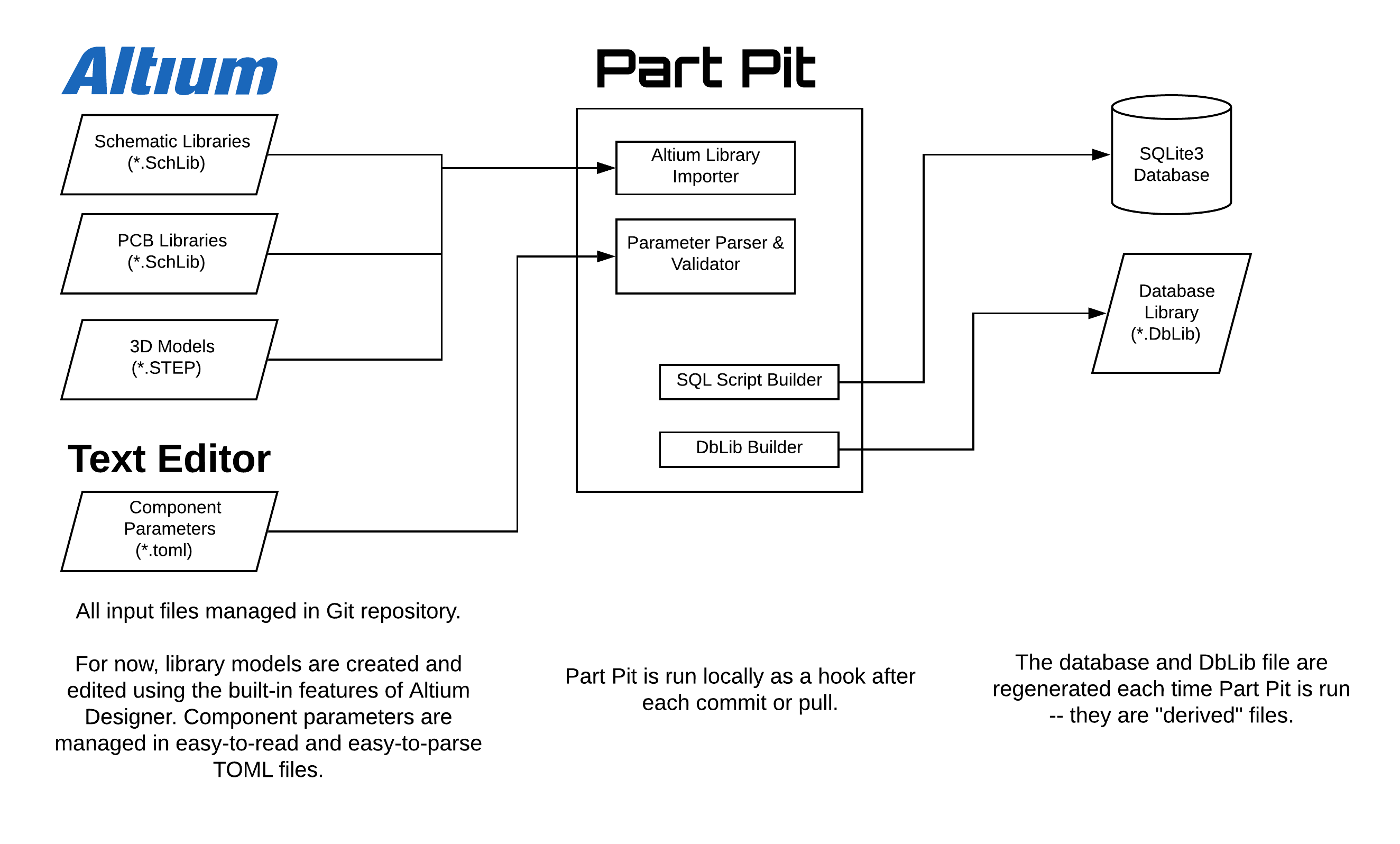
The purpose of this project is eventually to create a component library system that can be managed in a Git repository with entirely text-based description files. It also aims to be able to import from and export to any arbitrary CAD tool format. However, there are some external forces that are guiding the devleopment priorities of the project, so at first, it will be built to serve as an alternative to Altium's Vault system and will organize and manage Altium's proprietary binary library files. Component parameters will be defined using TOML, and the tool will use this data to link together the specified symbol / footprint / datasheets / parameters and produce an Altium DbLib file that links to a locally hosted SQLite3 database. This allows the library to function without internet access, and all changes to the library can be resolved using a collaborative git workflow.
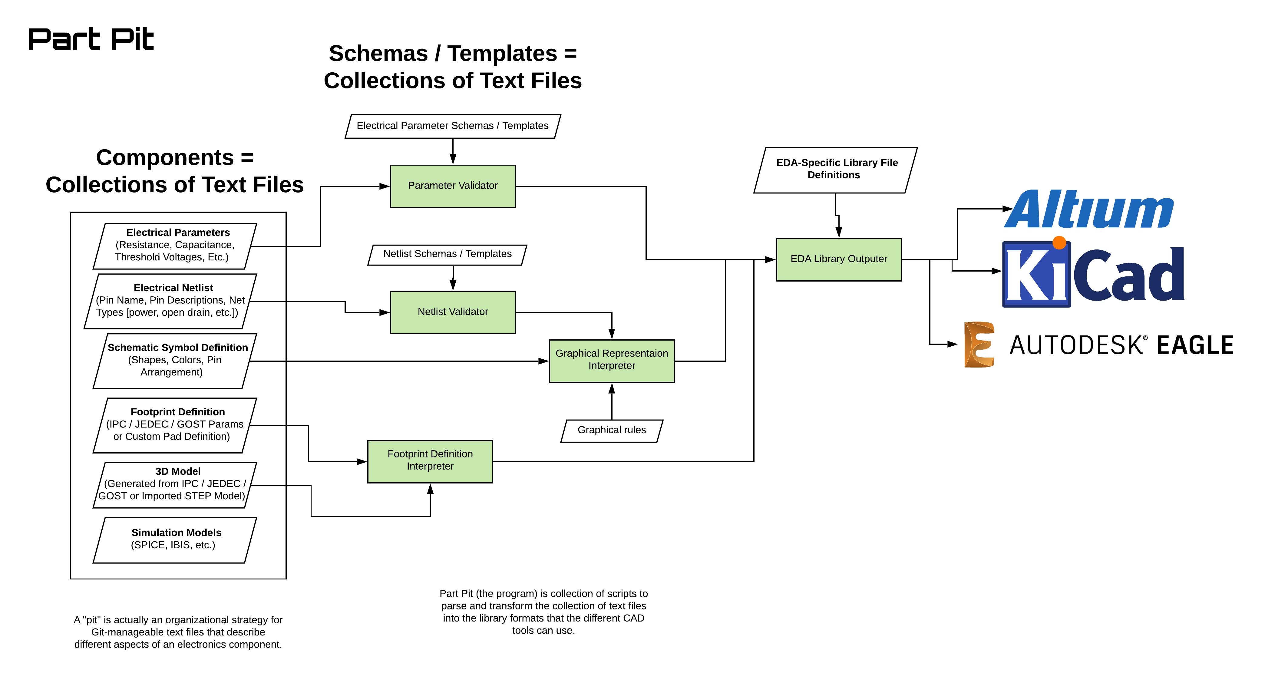
Eventually, I'd like Part Pit to serve a more generic role:
- Components are currently defined with TOML but eventually I'd like to support JSON, YAML, & maybe XML. The input format doesn't really matter, but it should be something that is easy to read, understand, and modify with a text editor
- Components all stored in a Git repository so you can do diffing & merge resolution using those tools, rather than the ECAD's interface.
- Written in Go
- Reads component file
- Validates correctness of the component file against a schema
- Generates a sqlite database with the component info
- Generates an Altium DbLib file formatted with sqlite table info
- Has ability to pull updates from the git server
- Digikey parametric search is something I want to add later
Schematic Symbols
Schematic symbols are graphical representations of electrical components that first and foremost need to communicate to humans the function of a circuit (as opposed to the physical arrangement). That means that a schematic not only needs to be correctly connected together for the sake of the EDA tool, it also needs to be legible and easy to understand for the sake of the designer. "Legible" and "easy to understand" open up a can of worms since style, convention, and aesthetics are subjective and differ between organizations, tools, and individuals.
As nice as it would be to define rigid rules that allow symbols to be defined programmatically (e.g. "all input pins go on the left side"), there are a too many "gotchas" and edge cases that provide exceptions to the rule in order to make the schematic capture cleaner (e.g. on switching power supply ICs, the feedback pin is an input, but almost always looks better to place it close to the output inductor on the right side).
So, in Part Pit, schematic symbols are separated conceptually between the following
- Electrical model (pin names, pin designators, ERC rule classes)
- Graphical model (pin decorators for clocks, active-low signals, etc; physical placement of pins)
- Fuzzy Rules / "Suggestions" (e.g. "VCC pins normally go near the top", "inputs normally go on the left", etc.) that provide sane defaults for positioning pins on new symbols, but allows the designer to move things around

