EMS-ESP-Boiler is a project to build a controller circuit running with an ESP8266 to communicate with EMS (Energy Management System) based Boilers and Thermostats from the Bosch range and compatibles such as Buderus, Nefit, Junkers etc.
There are 3 parts to this project, first the design of the circuit, second the code for the ESP8266 microcontroller firmware and lastly an example configuration for Home Assistant to monitor the data and issue direct commands via MQTT.
- EMS-ESP-Boiler
My original intention for this home project was to build a custom smart thermostat that interfaces with my Nefit Trendline HRC30 boiler and have it controlled via a mobile app using Home Assistant. I had a few cheap ESP32s and ESP8266s microcontrollers lying around from previous IoT projects and learning how to build a circuit to decode the EMS messages seemed like a nice challenge.
Firstly, some acknowledgments and kudos to the following people who have open-sourced their projects which have helped me tremendously:
susisstrolch - Probably the first working version of the EMS bridge circuit I found designed for the ESP8266. I borrowed Juergen's schematic and parts of his code logic for reading telegrams.
bbqkees - Kees built a working circuit and some sample Arduino code to read from the EMS and push messages to Domoticz. His SMD board is also now available for purchase.
EMS Wiki - A comprehensive reference (in German) for the EMS bus which is a little outdated, not 100% accurate and unfortunately no longer maintained.
Most Bosch branded boilers that support the Logamatic EMS (and EMS+) bus protocols work with this design. This includes Nefit, Buderus, Worcester and Junkers (all copyrighted). Please make sure you read the Disclaimer carefully before sending ambiguous messages to your EMS bus as you could cause serious damage to your boiler or thermostat.
I've tested the code and circuit with a few ESP8266 development boards such as the Wemos D1 Mini, Wemos D1 Mini Pro, Nodemcu0.9 and Nodemcu2 dev boards. It will also work on bare ESP8266 chips such as the ESP-12E but do make sure you disabled the LED support and wire the UART correctly as the code doesn't use the normal Rx and Tx pins. Why is explained later.
- Either build the circuit below or purchase a ready built board from bbqkees via his GitHub page or the Domoticz forum.
- Get an ESP8266 dev board and connect the 2 EMS output lines from the boiler to the circuit and the Rx and Tx out to ESP pins D7 and D8 respectively. The EMS connection can either be the 12-15V AC direct from the thermostat bus line or from the 3.5" Service Jack at the front.
- Optionally connect an external LED or decide to use the onboard ESP8266 LED. This will flash when there is an error on the EMS bus line or stay solid when it's connected.
- Modify
my_custom.h - Build and upload the firmware to the ESP8266 device. I used Platformio with Visual Studio Code but using Atom or a command-line is just as easy if you don't plan to make code changes. Do make sure you set the MQTT and WiFi credentials correctly in the build flags and if you're not using MQTT leave the MQTT_IP blank. The firmware supports OTA too with the default hostname as 'boiler'.
- Power the ESP either via USB or direct into the 5v vin pin from an external power 5V volts supply with min 400mA.
- Attach the 3v3 out on the ESP8266 to the DC power line on the EMS circuit as indicated in the schematics.
- The WiFi connects via DHCP by default. Find the IP by from your router and then telnet (port 23) to it. If a connection can't be made it will go into Access Point mode. Tip: to enable Telnet on Windows run
dism /online /Enable-Feature /FeatureName:TelnetClientor install something like putty. If everything is working you should see the messages appear in the window as shown in the next section. However if you're unable to locate the IP of the ESP then something went wrong. Re-compile with the -DDEBUG_SUPPORT and connect via USB to a PC and check the Serial log for errors.
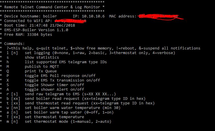
Use the telnet client to inform you of all activity and errors real-time. This is an example of the telnet output:
If you type 'l 4' and Enter, it will toggle verbose logging showing you more detailed messages. I use ANSI colors with white text for info messages, green for well formatted telegram packages (which have validated CRC checks), red for corrupt packages and yellow for send responses.
To see the current values of the Boiler and its parameters type 's' and hit Enter. Watch out for unsuccessful telegram packets in the #CrcErrors line.
Commands can be issued directly to the EMS bus typing in a letter followed by an optional parameter and pressing Enter. Supported commands are:
- b to send a read command to the boiler. The 2nd parameter is the type. For example 'b 33' will request type UBAParameterWW and bring back the Warm Water temperatures from the Boiler.
- t is similar, but to send a read command to the thermostat.
- T set the thermostat temperature to the given celsius value
- w to adjust the temperature of the warm water from the boiler
- a to turn the warm tap water on and off
- h to list all the recognized EMS types
- P to toggle the Polling response on/off (note it's not necessary to have Polling enabled to work)
- m to set the thermostat mode to manual or auto
- S to toggle the Shower Timer functionality on/off
- A to toggle the Shower Timer Alert functionality on/off
Disclaimer: be careful when sending values to the boiler. If in doubt you can always reset the boiler to its original factory settings by following the instructions in the user guide. On my Nefit Trendline HRC30 that is done by holding down the Home and Menu buttons simultaneously for a few seconds, selecting factory settings from the scroll menu and lastly pressing the Reset button.
The EMS circuit is really all credit to the hard work many people have done before me, noticeably susisstrolch with his ESP8266 version.
I've included a prototype boards you can build yourself on a breadboard. One part for only reading values from the Boiler and an extension with the write logic so you can also send commands.
We need the Rx/Tx of the ESP8266 for flashing, so the code in emsuart.cpp switches the UART pins to use RX1 and TX1 (GPIO13/D7 and GPIO15/D8 respectively). This also prevents any bogus stack data being sent to EMS bus when the ESP8266 decides to crash like after a Watch Dog Reset.
The breadboard layout was done using DIY Layout Creator and sources files are included in this repo.
The schematic used (as designed by susisstrolch):
Optionally I've also added 2 0.5A/72V polyfuses between the EMS and the two inductors L1 and L2 for extra protection.
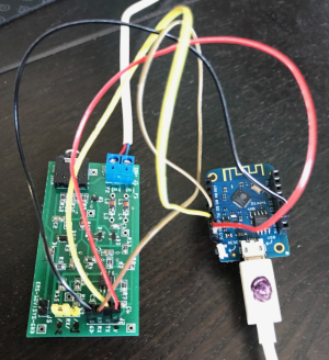
And lastly if you don't fancy building the circuit, bbqkees can sell you one complete with SMD components which looks like the photo below when connected to a Wemos D1 Mini:
The EMS circuit will work with both 3.3V and 5V. It's easiest though to power directly from the ESP8266's 3V3 line and run a steady 5V into the microcontroller. Powering the ESP8266 microcontroller can be either:
- via the USB if your dev board has one
- using an external 5V power supply into the 5V vin on the board
- powering from the 3.5" service jack on the boiler. This will give you 8V so you need a buck converter (like a Pololu D24C22F5) to step this down to 5V to provide enough power to the ESP8266 (250mA at least)
- powering from the EMS line, which is 15V A/C and using a buck converter as described above. Note the current design has stability issues when sending packages in this configuration so this is not recommended yet if you plan to many send commands to the thermostat or boiler.
| With Power Circuit |
|---|
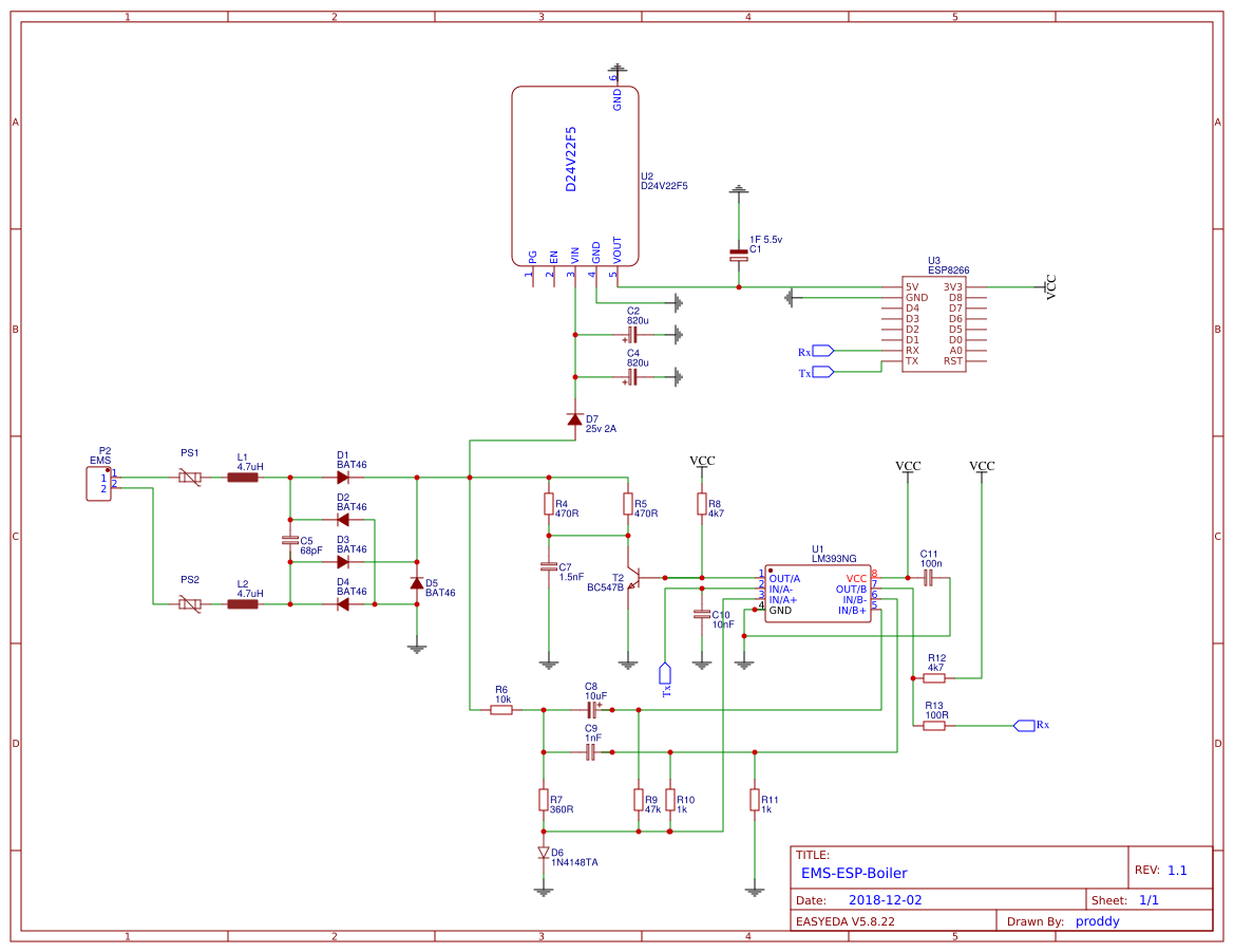 |
Packages are sent to the EMS "bus" from the Boiler and any other compatible connected devices via serial TTL transmission. The protocol is 9600 baud, 8N1 (8 bytes, no parity, 1 stop bit). Each package is terminated with a break signal <BRK>, a 11-bit long low signal of zeros.
A package can be a single byte (see Polling below) or a string of 6 or more bytes making up an actual data telegram. A telegram is always in the format:
[src] [dest] [type] [offset] [data] [crc] <BRK>
I reference the first 4 bytes as the header in this document.
Each device has a unique ID.
The Boiler has an ID of 0x08 (type MC10) and also referred to as the Bus Master or UBA.
My thermostat, which is a* Moduline 300* uses the RC30 protocol and has an ID 0x17. If you're using a RC35 type thermostat such as the newer Moduline 300s or 400s use 0x10 and make adjustments in the code as appropriate. bbqkees did a nice write-up on his github page here.
Our circuit acts as a service key and thus uses an ID 0x0B. This ID is reserved for special devices intended for installation engineers for maintenance work.
The bus master (boiler) sends out a poll request every second by sending out a sequential list of all possible IDs as a single byte followed by the break signal. The ID always has its high 8th bit (MSB) set so in the code we're looking for 1 byte messages matching the format [dest|0x80] <BRK>.
Any connected device can respond to a Polling call with an acknowledging by sending back a single byte with its own ID. In our case we would listen for a [0x8B] <BRK> (meaning us) and then send back [0x0B] <BRK> to say we're alive and ready. Although I found this is not needed for normal operation so it's disabled as default in the code.
Polling is also the trigger to start transmitting any packages queued for sending. It must be done within 200ms or the bus master will time out.
When a device is broadcasting to everyone there is no specific destination needed. [dest] is always 0x00.
The tables below shows which types are broadcasted regularly by the boiler (ID 0x08) and thermostat (ID 0x17). The data length is excluding the 4 byte header and CRC and the Name references those in the ems wiki.
| Source (ID) | Type ID | Name | Description | Data length | Frequency |
|---|---|---|---|---|---|
| Boiler (0x08) | 0x34 | UBAMonitorWWMessage | warm water temperature | 19 bytes | 10 seconds |
| Boiler (0x08) | 0x18 | UBAMonitorFast | boiler temps, power, gas/pump switches | 25 bytes | 10 seconds |
| Boiler (0x08) | 0x19 | UBAMonitorSlow | boiler temp and timings | 22 bytes | 60 seconds |
| Boiler (0x08) | 0x1C | UBAWartungsmelding | maintenance messages | 27 bytes | 60 seconds |
| Boiler (0x08) | 0x2A | n/a | status, specific to boiler type | 21 bytes | 10 seconds |
| Boiler (0x08) | 0x07 | n/a | ? | 21 bytes | 30 seconds |
| Source (ID) | Type ID | Name | Description | Frequency |
|---|---|---|---|---|
| Thermostat (0x17) | 0x06 | RCTime | returns time and date on the thermostat | 60 seconds |
| Thermostat (0x17) | 0x91 | RC30StatusMessage | returns current and set temperatures | 60 seconds |
| Thermostat (0x17) | 0xA3 | RCTempMessage | returns temp values from external (outdoor) sensors | 60 seconds |
Refer to the code in ems.cpp for further explanation on how to parse these message types and also reference the EMS Wiki.
Telegram packets can only be sent after the Boiler sends a poll to the sending device. The response can be a read command to request data or a write command to send data. At the end of the transmission a poll response is sent from the client (<ID> <BRK>) to say we're all done and free up the bus for other clients.
When doing a request to read data the [src] is our device (0x0B) and the [dest] must have has it's MSB (8th bit) set. Say we were requesting data from the thermostat we would use [dest] = 0x97 since RC30 has an ID of 0x17.
Following a write request, the [dest] doesn't have the 8th bit set and after this write request the destination device will send either a single byte 0x01 for success or 0x04 for failure.
Every telegram sent is echo'd back to Rx.
Disclaimer: This code here is really for reference only, I don't expect anyone to use "as is" since it's highly tailored to my environment and my needs. Most of the code however is self explanatory with comments here and there in the code.
The code is built on the Arduino framework and is dependent on these external libraries:
- Time http://playground.arduino.cc/code/time
- PubSubClient http://pubsubclient.knolleary.net
- ArduinoJson https://github.com/bblanchon/ArduinoJson
- CRC32 https://github.com/bakercp/CRC32
emsuart.cpp handles the low level UART read and write logic. You shouldn't need to touch this. All receive commands from the EMS bus are handled asynchronously using a circular buffer via an interrupt. A separate function processes the buffer and extracts the telegrams. Since we don't send too many write commands this is done sequentially. I couldn't use the standard Arduino Serial implementation because of the 11-bit break signal causes a frame-error which gets ignored.
ems.cpp is the logic to read the EMS packets (telegrams), validates them and process them based on the type.
boiler.ino is the Arduino code for the ESP8266 that kicks it all off. This is where we have specific logic such as the code to monitor and alert on the Shower timer and light up the LEDs. LED support is enabled by default and can be switched off at compile time using the -DNO_LED build flag.
my_config.h all the custom settings
MyESP.cpp is my custom library to handle WiFi, MQTT, MDNS and Telnet. Uses a modified version of TelnetSpy (https://github.com/yasheena/telnetspy)
ems.cpp defines callback functions that handle all the broadcast types listed above (e.g. 0x34, 0x18, 0x19 etc) plus these extra types:
| Source (ID) | Type ID | Name | Description |
|---|---|---|---|
| Boiler (0x08) | 0x33 | UBAParameterWW | reads selected & desired warm water temp |
| Boiler (0x08) | 0x14 | UBATotalUptimeMessage | |
| Boiler (0x08) | 0x15 | UBAMaintenanceSettingsMessage | |
| Boiler (0x08) | 0x16 | UBAParametersMessage | |
| Thermostat (0x17) | 0xA8 | RC20Set | sets operating modes for an RC20 |
| Thermostat (0x10) | 0xA7 | RC30Set | sets operating modes for an RC30 |
| Thermostat | 0x02 | Version | reads Version major/minor |
| Thermostat | 0x91, 0x41, 0x0A | Status Message | read monitor values |
In boiler.ino you can make calls to automatically request these types in the function regularUpdates().
I am still working on adding more support to known thermostats.
Currently known types and collected versions:
Moduline 300 = Type 77 Version 03.03 Moduline 400 = Type 78 Version 03.03 Buderus RC35 = Type 86 Version 01.15 Nefit Easy = Type 202 Version 02.19 Nefit Trendline HRC30 = Type 123 Version 06.01 BC10 = Type 123 Version 04.05
Read and write of setpoint temperature and mode are supported.
Read and write of setpoint temperature and mode are supported.
Note I found type's 3F, 49, 53, 5D are identical. So are 4B, 55, 5F and mostly zero's. Types 40, 4A, 54 and 5E are also the same.
An RC35 thermostat can support up to 4 heating circuits each controlled with their own Monitor and Working Mode IDs.
Fetching the thermostats setpoint temperature us by requesting 0x3E and looking at the 3rd byte in the data telegram (data[2]) and dividing by 2.
The mode is on type 0x47 (or 0x3D) and the 8th byte (data[7]). 0=off, 1=on, 2=auto
This is roughly supported but not fully tested.
There is limited support for an Nefit Easy TC100/TC200 type thermostat. The current room temperature and setpoint temperature can be read. What I'm still figuring out is how to read the mode and set the temperature values without sending http post commands to their web server.
- To configure for your thermostat and specific boiler settings, modify
my_config.h. Here you can- set flags for enabled/disabling functionality such as
BOILER_SHOWER_ENABLEDandBOILER_SHOWER_TIMER. - Set WIFI and MQTT settings, instead of doing this in
platformio.ini
- set flags for enabled/disabling functionality such as
- To add new handlers for EMS data types, first create a callback function and add to the
EMS_Typesarray at the top of the fileems.cppand modifyems.h
When the ESP8266 boots it will send a start signal via MQTT. This is picked up by Home Assistant and sends a notification informing me that the device has booted. Useful for knowing when the ESP gets reset.
I run Mosquitto on my Raspberry PI 3 as the MQTT broker.
The boiler data is collected and sent as a single JSON object to MQTT TOPIC home/boiler/boiler_data. A hash is generated (CRC32 based) to determine if the payload has changed, otherwise don't send it. An example payload looks roughly like:
{"wWCurTmp":"43.0","wWHeat":"on","curFlowTemp":"51.7","retTemp":"48.0","burnGas":"off","heatPmp":"off","fanWork":"off","ignWork":"off","wWCirc":"off","selBurnPow":"0","curBurnPow":"0","sysPress":"1.6","boilTemp":"54.7","pumpMod":"4"}
Similarly the thermostat values are sent as a json package under a topic named home/boiler/thermostat_data with the current mode, room temperature and set temperature.
These topics can be configured in the TOPIC_* defines in boiler.ino. Make sure you change the HA configuration too to match.
Checking whether the shower is running is tricky. We know when the warm water is on and being heated but need to distinguish between the central heating, shower, hot tap and even a bath tap. So this code is a little experimental.
There is other logic in the code to compensate for water heating up to shower temperature and whether the shower is turned off and back on again quickly within a 10 second window.
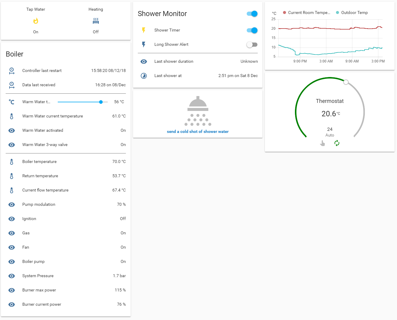
Within Home Assistant it renders as:
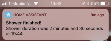
and the alerts on an iOS/Android device using PushBullet, PushOver or any notification service would look like:
You can find the .yaml configuration files under doc/ha. See also https://community.home-assistant.io/t/thermostat-and-boiler-controller-for-ems-based-boilers-nefit-buderus-bosch-using-esp/53382
On Windows:
- Download Git (install using the default settings)
- Download and install Visual Studio Code (VSC). It's like 40MB so don't confuse with the commercial Microsoft Visual Studio.
- Restart the PC (if using Windows) to apply the new PATH settings. It should now detect Git
- Install these VSC extensions: PlatformIO IDE & GitLens, and then click reload to activate them
- Git clone this repo, eith using
git clonefrom PlatformIO's terminal or the Git GUI interface - Create a
platformio.inibased on theplatformio.ini-examplemaking the necessary changes for your WiFi and MQTT credentials in the build flags. If you're not using MQTT leave MQTT_IP empty (MQTT_IP="")
On Linux (e.g. Ubuntu under Windows10):
- make sure Python 2.7 is installed
- make sure you have a Linux distro installed (https://docs.microsoft.com/en-us/windows/wsl/install-win10)
- Do:
% pip install -U platformio
% sudo platformio upgrade
% platformio platform update

% git clone https://github.com/proddy/EMS-ESP-Boiler.git
% cd EMS-ESP-Boiler
% cp platformio.ini-example platformio.ini- edit
platformio.inito setenv_defaultand the flags likeWIFI_SSID WIFI_PASSWORD, MQTT_IP, MQTT_USER, MQTT_PASS. If you're not using MQTT leave MQTT_IP empty (MQTT_IP="")
% platformio run -t uploadPorting to the Arduino IDE can be a little tricky but it is possible.
- Add the ESP8266 boards (from Preferences add Additional Board URL
http://arduino.esp8266.com/stable/package_esp8266com_index.json) - Go to Boards Manager and install ESP8266 2.4.x platform
- Select your ESP8266 from Tools->Boards and the correct port with Tools->Port
- From the Library Manager install the needed libraries from platformio.ini
- The Arduino IDE doesn't have a common way to set build flags (ugh!) so you'll need to un-comment these lines in
boiler.ino:
#define WIFI_SSID "<my_ssid>"
#define WIFI_PASSWORD "<my_password>"
#define MQTT_IP "<broker_ip>"
#define MQTT_USER "<broker_username>"
#define MQTT_PASS "<broker_password>"- Put all the files in a single sketch folder (
ESPHelper.*, boiler.ino, ems.*, emsuart.*) - cross your fingers and hit CTRL-R to compile...
If the WiFi, MQTT, MDNS or something else fails to connect, re-build the firmware using the -DDEBUG_SUPPORT option, connect the ESP8266 to a USB in your computer and monitor the Serial output. A lot of detailed logging will be printed to help you pinpoint the cause of the error.
The onboard LED will flash if there is no connection with the EMS bus. You can disable LED support by adding -DNO_LED to the build options.
Some annoying issues that need fixing:
- Very infrequently an EMS write command is not sent, probably due to a collision somewhere in the UART between an incoming Rx and a Poll. The retries in the code fix this for now.
- Measure amount of gas in m3 per day for the hot water vs the central heating, and convert this into cost in Home Assistant
- Support changing temperatures on an Nefit Easy. To do this you must send XMPP messages directly to the thermostat. There is already a TCP stack and a Wifi and Telnet server running in the code, so the building blocks are there to extend with another XMPP client. Here are a number of Python based projects that show how to do this:
- Store custom params like wifi credentials, mqtt, thermostat type on ESP8266 using SPIFFS
- Add support for a temperature sensor on the circuit (DS18B20)
Any comments, suggestions or code contributions are very welcome. Please post a GitHub issue.
This code and libraries were developed from information gathered on the internet and many hours of reverse engineering the communications between the EMS bus and thermostats. It is not based on any official documentation or supported libraries from Buderus/Junkers/Nefit (and associated companies) and therefore there are no guarantees whatsoever regarding the safety of your devices and/or their settings, or the accuracy of the information provided.

