 |
 |
- Ramp-up Time: 5 seconds to achieve 200°C
- Measurement Accuracy: up to ±5%
- Power: 75W
- Instability (Consistency) of Set Temperature: ±0.2°C
- Temperature Range: 0 – 500°C (from room temperature)
- Number of ADC Samples: 250
- Measurement Time / Percentage of Measurement Duration (Heating Off): 1.4ms / 1.4% (or 0.9ms / 0.9% for temperatures >150°C)
- PWM Frequency / Measurement Frequency: 50Hz / 10Hz
- Other: (futures below)
- T12 Tips Compatibile
- IPS Display
- Current and Set Temperature in
°C - Power Output Bar Indicator
- Settings (PID and GUI)
- Current and Set Temperature in
- Rotary Encoder
- Touch Button (stop/start heating)
- Heating LED
- Switch 230VAC
- Front Panel - PCB made
- Connector GX16 (easy tips replacement)
- Efficient Temperature Setting - PID Controller
- Memory - Eeprom
- Autosleep (todo)

 |
stlink, kicad (optional)
It's required debuger for flash STM32. STLINK-V2 clone is fine.
st-flash --reset write soldering-*.bin 0x08000000If you have error then it's probably stm32 clone. It's ok. Blue-Pill boards have clons often. Check st-info --chipid. For clones "chipid" is 0 instead 0x0410 or similar. Try to flash with my config file.
st-flash -c doc/BP_clone.cfg --reset write soldering-*.bin 0x08000000-
First take a look at overall BOM below. Next check PCB BOM online or as file in
PCB/{version}/bom/ibom.html. (I suggest to dowload the repo this point)Part Description Photo PCB components All important components from PCB BOM Housing Gainta G762 Power Supply 24V 24V/3A or more current (e.g. 24V/4A) 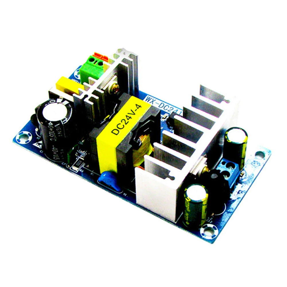
Power Supply 5V 5V/100mA or more current MCU Blue Pill board Display ST7735 SPI 160x80 0.96" module 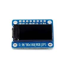
Encoder Rotary Encoder module 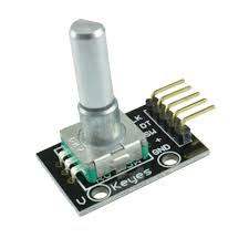
Soldering Iron Socket GX16-5 Socket Front Panel PCB front panel (project in repo folder) Knob Knob for encoder AC Switch SPDT Other components LED or duoLED 3mm, 2x 1nF THT Make sure u have all what you need to DIY. Good to check all parts works berore u start assembly
-
If u making PCB by own, remember to:
- Protect copper by e.g. Rosin
- Solder wires from "F.cu" layer (may be before drilling, except two connections)
If u order PCB, remember u can also order PCB-front-board together
-
Soldering SMD (after drilling) - BOM online or
PCB/*/bom/can help -
Soldering THT
-
Mount 24V power supply to device housing and make separation between PCB (Plan this housing from mountings things inside)
-
Make power wires from overall schematic for: Switch, Power suplies, AC connector (Isolate 230V wires and connections)
-
Make wires and solder from overall schematic (for: Display, Encoder, etc) and add 2x 1nF to Encoder module if there is no capacitors
-
Isolate and Mount (glue) 5V power supply
-
Connect all together, burn binary and check that's working
-
Glue OLED while device works (it would be easier to nice match) to (if u have) PCB-front-board.
-
Let's put everything together now


-
Be careful with AC Power
-
required tools:
- some working soldering iron (it's funny, but not ironically)
- some glue (e.g. hotglue or b7000)
- drilling machine, drills: ~3mm, 0,7mm, 0,9mm (look at kicad brd)
- tweezer
- (optional) crimping tool for Dupont Connectors
-
good to use:
- 2.54mm angle pin header + Dupont female Connectors
-
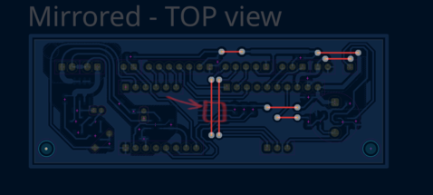
Front Panel
U have to order PCB or drill by CNC. Alternativly try to print 'cut edges' on paper and cut housing plastic plate by knife / drill. The G762 housing have bit soft plastic (maybe ABS) - front/back plates.


Check the Pictures/ folder! :)
What I decide to leave at concept phase:
- 907 tips compatibility
- tips recognizing
- measurement of thermocouple cold junction thermistor
- optional li-ion power
Feel free to open Pull Request or some Issue
