STG Business Card
UPDATE!
I am working on some updates to the STG Business Card project.
- Adding additional options of form-factor/materials.
- Adding Through-Hole and SMD versions.
- Reworking of the project structure.
Motive
The motive behind this project is to provide to prospective employers an example of my pcb work in a form factor that is easy for them to carry around. I came up with the idea of putting a simple Stepped Tone Generator onto a PCB the size of a business card after watching a video from Look Mum No Computer, where he builds an Atari Punk Console (Stepped Tone Generator).
PCB Design
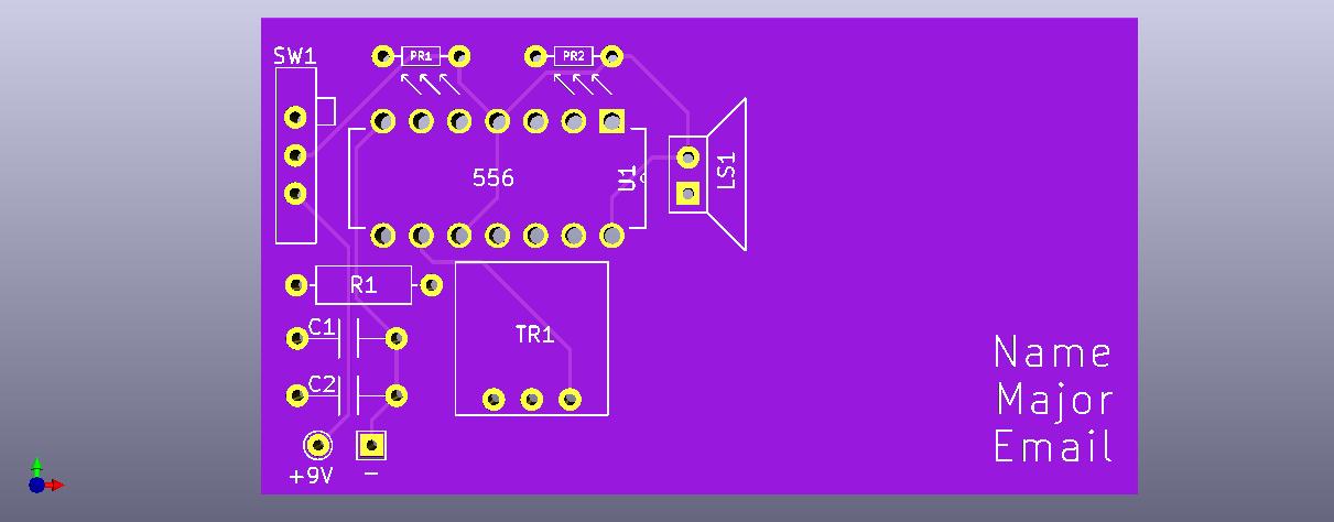
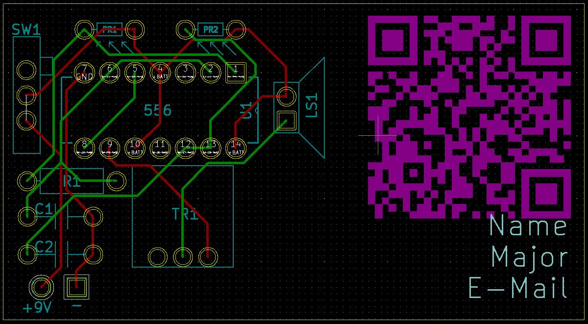
Using the same instructables guide from BrownDogGadgets, I used KiCad to draw up the schematic and designed a PCB to go with it. The PCB is a 2-layer design with through-hole components. Below are pictures of the 3D model and the PCB layout in KiCad.
Bill of Materials
| Description | Ref | Component Value | Part # | Link |
|---|---|---|---|---|
| Resistor | R1 | 1K | CFR-25JB-52-1K | Digi-key |
| Capacitor | C1, C2 | 0.22u | K224M20X7RF53H5 | Mouser |
| 556 Timer | U1 | 556 | NE556N | Mouser |
| IC Socket | U1 | 14 Pin DIP | ICS-314-T | Digi-Key |
| Photoresistor | PR1, PR2 | 1k - 10k | 161 | Adafruit |
| Trimmer Resistor | TR1 | 5k | 3386T | Mouser |
| Speaker | LS1 | 8 ohm | 1890 | Adafruit |
| Switch | SW1 | SPDT | 805 | Adafruit |
| 9V Battery Clip | Batt/9V | 9V | 235 | Mouser |
Assembly Order
For ease of assembly, start with the lower profile components and work up to the higher profile components.
I assembled the circuit in this order:
- Resistor and Photoresistors
- IC Socket
- Capacitors
- Switch
- Potentiometer
- Speaker and Battery Clip
- IC
Assembled Circuit
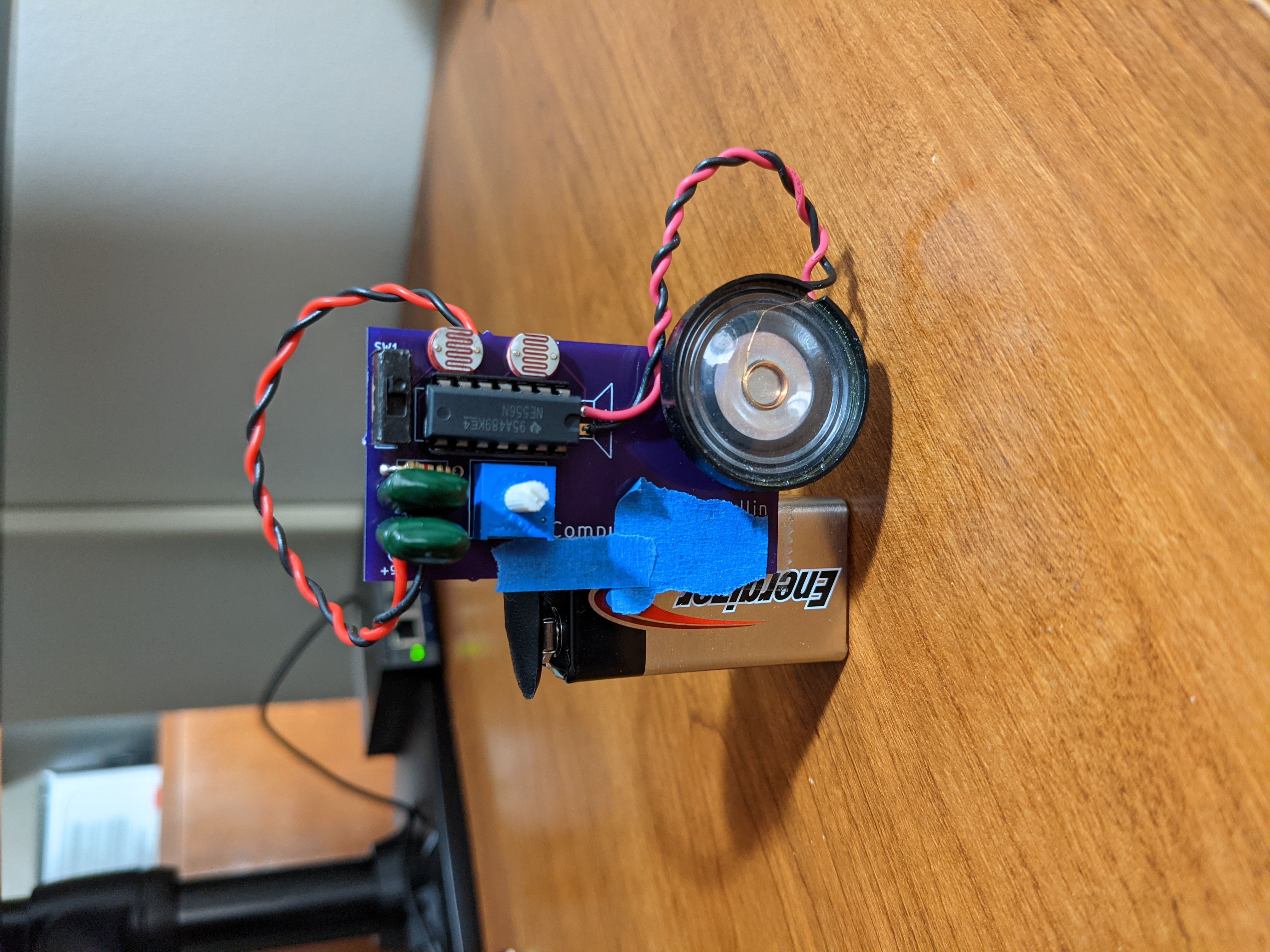
Below is an assembled STG circuit. A demo of the circuit can be found here: STG Demo

Postmortem
Overall, I happy with the final product. However, I may add an additional PCB, to this project, that swaps out the photoresistors for potentiometers. Alternate version has been added. However, it is untested.
For the alternate design, below are the parts that have changed.
- TR2 & TR3 = 500k ohms
- C1 & C2 = 0.01 uF

