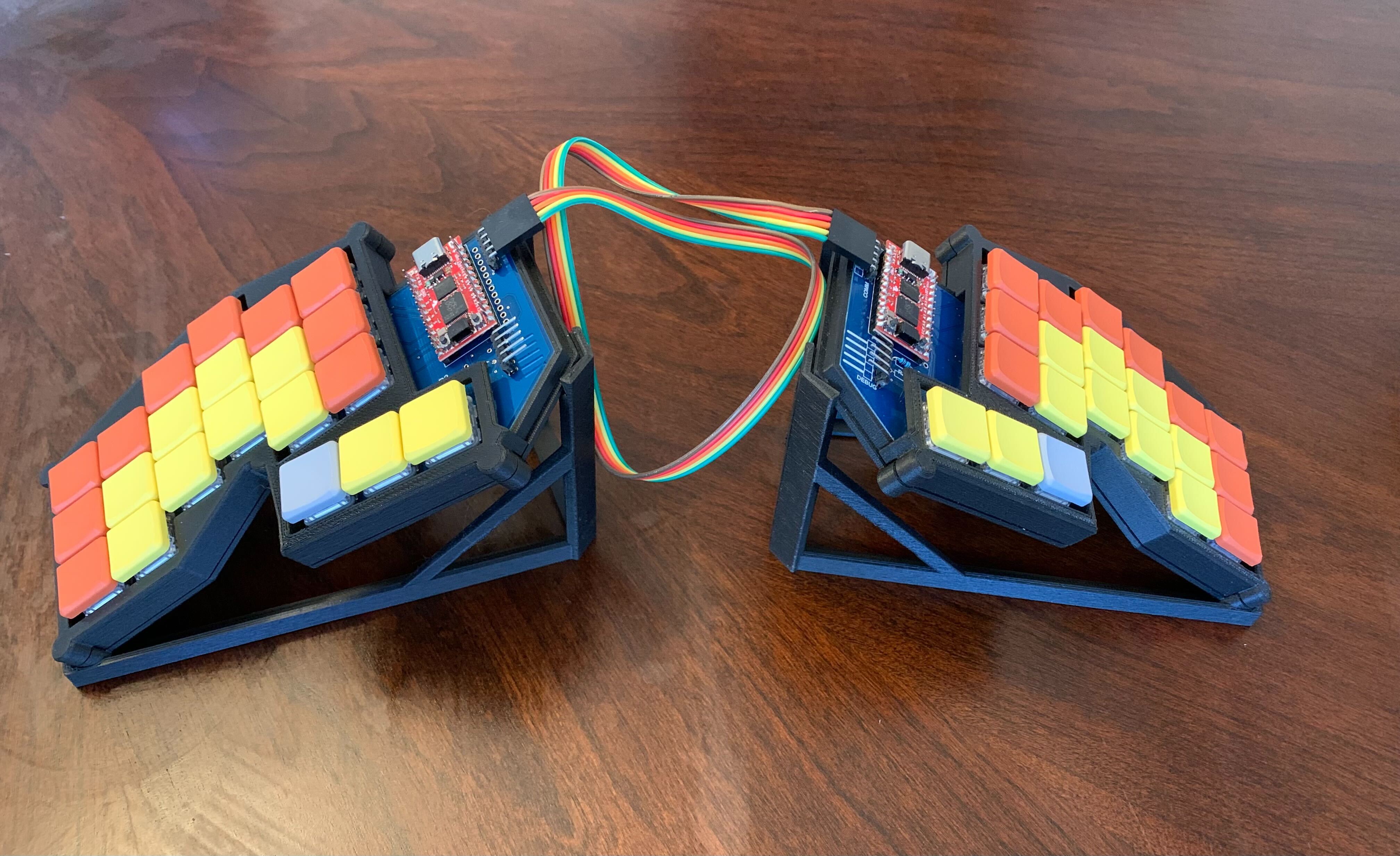
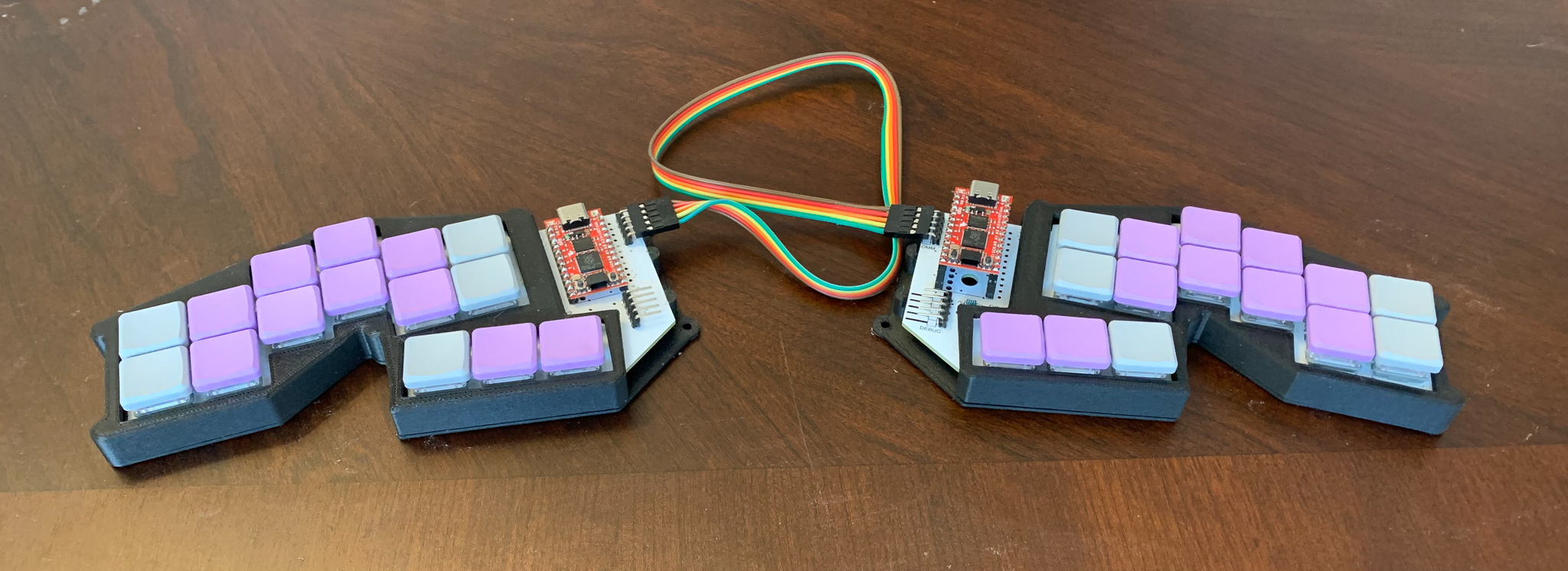
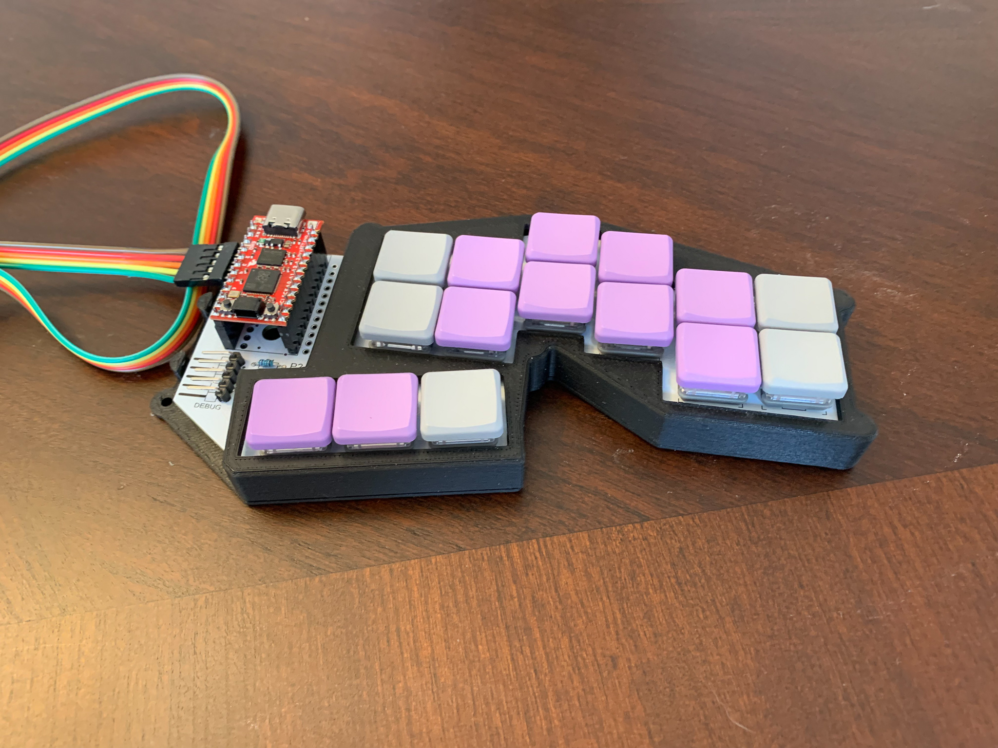
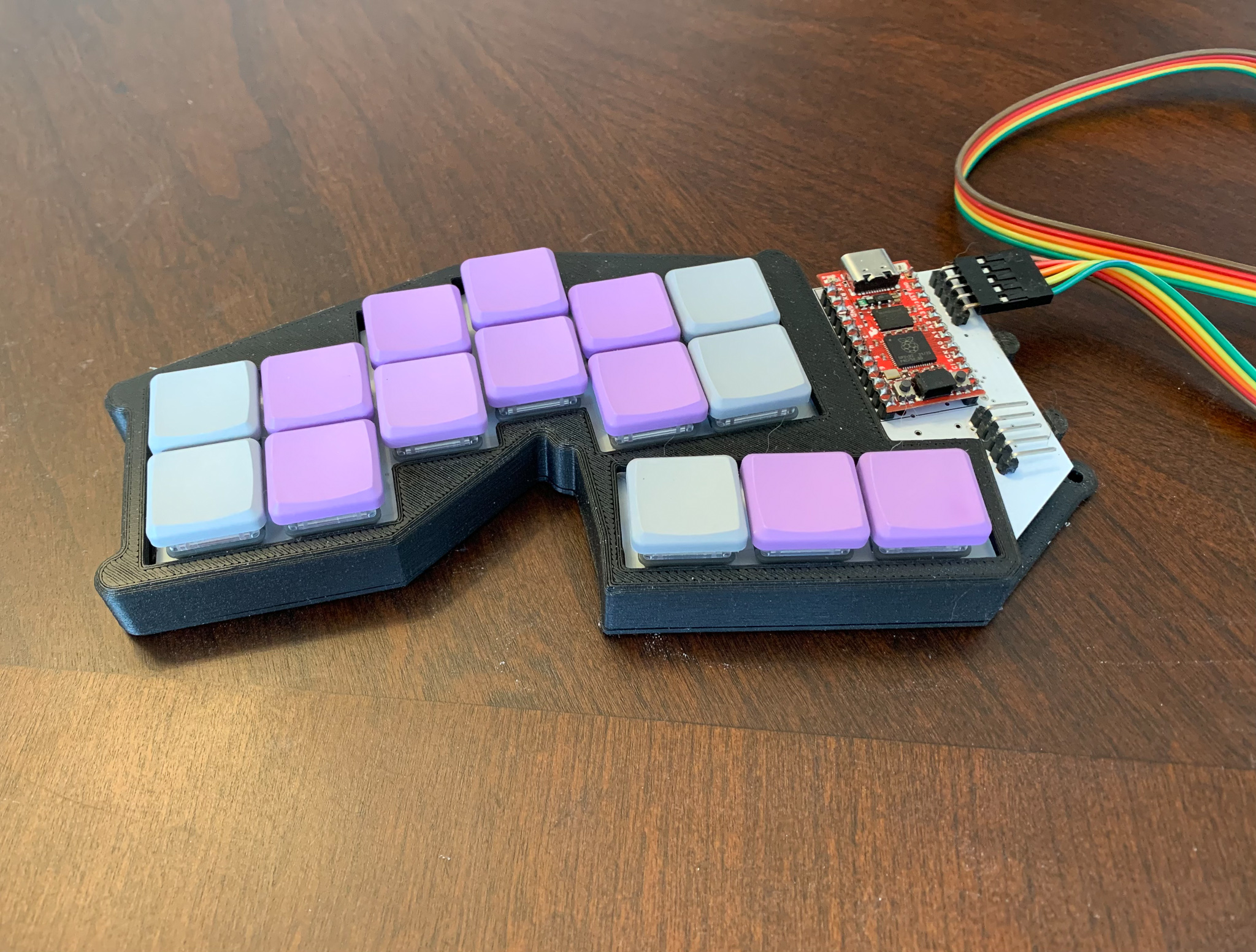
This repo captures the design files associated with my custom keyboards.
These keyboards are primarily focused on Steno input, mainly using Plover. In the spirit of open steno, I have made these designs open. Anyone is free to make designs based on these keyboards, for non-commercial purposes. I am releasing the designs under the CC BY-NC 3.0 license. Specifically, this means if you wish to sell a product based on the design, you should talk to me.
This is basically the same design as the proto2, but with a third row. The qmk supports an easier qwerty mode, but still with a modified homerow modifier support (I use the lower row as it has slightly fewer rollover conflicts).
The BOM is the same as the proto2, but it will need 42 diodes.
For lack of a better name, this first design is called the "proto2".
There was an earlier prototype, that was handwired, and rather fragile. This is the first version I would consider to be a usable keyboard. In the above pictures, the left half has the MCU (Pro Micro RP2040) soldered directly to a header, soldered to the PCB, and the right one uses a socket.
To build this, in addition to the PCBs, you will need
- 2 Pro Micro RP2040 boards. At the time of my build, these are running about $11, and seem readily available.
- 30 Kailh Choc switches. I sourced mine from Mkultra. I recommend the "pink" version, which has 20gf springs, and I find work well.
- 30 keycaps for these switches. I used the MBK Factory Colors keycaps, which allows me to make the "primary" keys stand out a little, and just looks rather nice.
- 30 general purpose SOD123 diodes. I got BAV19W, although almost any diode will work for this.
- 2 or 4 5-pin right angle headers. Two are needed for the communication between the boards. The others are interested if you want to use SWD, since the RP2040 Pro Micro inconveniently puts these connectors on the underside of the board.
The PCB is reversable. The RP2040 board should be mounted in the labeled holes, which is always the left set when viewed from the top. The diodes are intended to be soldered to the bottom side of the board.
I have also a case design that can be 3d printed. The models are for the right side. Use your slicing software to mirror about the X axis to print the pieces for the other side.
The firmware I am using for this keyboard is in my fork of QMK.


