
Open Maker's Cube is an open source project developed for making electronics project design and testing more fun and convenient. Due to its versatile design, the Maker's Cube can be used for other hobbies and applications.
The itch needing scratching is the ratsnest of wires and cables generated when building electronics bread board circuits. I frequently use Raspberry Pis and other microcontrollers/SBCs. With these devices comes the need for power strips which quickly leads to a maze of entangled power cords.
Portability of any electronics project can be an issue. If a project is built on the kitchen table for example, relocating requires a lot of disconnecting and re-routing. Inevetibly wires came loose from the breadboards, resulting in needless troubleshooting.
Ergonomically, bending over and wiring breadboard circuits for hours is hard on the back and neck. Adequate Lighting can also be a concern.
The Maker's cube is lightweight. Around 3.5 lbs base unit only and is less than 7 lbs fully loaded with hardware(Rpi's/Arduinos, electronic components, plugin power supplies).
The dimensions are 200mm (8in.) x 200mm (8in.) x 200mm (8in.). This size is perfect for any desk or table. Not taking up any more space than a typical laptop.
The frame is made out of lightweight 1 in. square aluminum tubing. In early designs, 80/20 was used, but added almost 2x the weight.
M3 Threaded aluminum inserts are inserted into the aluminum frame to hold the components securely. The threaded inserts do require a rivet insertion tool. There are a lot of rivets, so inserting rivets into the frame is the most time consuming process.
All plastic parts (orange) are printed with PETG. I went with PETG to hopefully withstand the heat better. Especially in the summer months. Obviously, print in any material to fit your needs.
There are mounting plates to support Raspberry PIs and Arduino UNOs in both landscape and portrait orientations. Due to the flexibility of the DIN Rail clips, you can design any mounting plate for any device which can easily be attached to the DIN rail clips using two 2 - 3mm securing screws.
There is a mounting plate which holds a standard 400 pt solderless breadboard in both landscape and portrait orientations.
Mounted in the center of the Maker's cube is a 6 outlet power strip with 4 - 2.4A USB ports. This allows for mulitple electrical plugins inside the cube keeping the corded 'ratsnest' inside the body of the cube. The power strip has an extra long 9.8 ft cord.
By design, only M3 screws are used. This requires only a simple 2.5mm allen key, which I leave inside the tray. The DIN rail mounting clips can normally be removed by hand. However, if there are a lot of mounted components, the only other tool needed is a small flat tipped screwdriver to unlock the clips.
I use 6 inch plastic wire ties to keep the cables/wires organized inside the Maker's cube body.
There is a removable stand (prop) which is used to tilt the cube back at a 30 deg angle which allows the user to work at a comfortable eye level.
The detachable LED magnifier lamp is extremely handy. It is super bright and having a magnifier lens makes it extremely easy to see the intricate details.
As an after thought, I designed a crude helping hands assembly. It uses 3mm aluminum armature wire and conventional alligator clips. This is helpful if you need to solder or hold components. Yes, the wire will eventually break with excessive bending back-and-forth, but the wire is cheap and can be easily replaced.
I use 3M's 'Dual Lock' fastener tape to secure the power supply to the inside bottom frame of the cube. The allows the power supply to be easily removed if need be. Also, the front 'prop' stand which tilts the cube at an angle, uses small sections of this tape to secure itself inside the cube's inner frame for transport.
To be extremely modular and flexible I designed the DIN Rail clips to be generic by nature. There two 3mm threaded inserts for mounting external components. The idea is you can design and mount anything you'd like to the clip.
I began the CAD design work in Sketchup. However, since I wanted to release as a open source project, I migrated the CAD design over to OpenScad. I relied heavlily on these wonderful open source projects:
- NopSCADlib - nophead, thanks so much for contributing this library! Absolutely amazing and a huge time saver for generating this beautiful documentation.
- BOSL
- Dimlines - A dimensioning library
- objectarrays
- MCAD
- Obiscad
- Textgenerator
- Shimonbox
- Openscad-threads
- Chamfersfor OpenScad
- BOLTS
- Din Rail Inspiration RobertHunt Thingiverse
Thank you to the authors of these libraries. I may not have used all them directly in this project, but have gained inspiration from all. I may have used other libraries which I have not given credit. If so, please contact me and I'll update the list. I'm relatively new to OpenScad programming, so my code is not perfect and not always fully parameterized.
In summary, Maker's Cube goal is to address the following concerns:
- Portability Contain the electronics project in one location and easy to transport. A fully loaded cube weighs less than 6 lbs.
- Less back strain You can comfortably work on your projects in a seated position, eliminating the need to bend over a table/desk for hours.
- Less eye strain There is a flexible super bright LED lamp mounted to the cube with a 1.5X magnifier glass.
- Modularity Due to the Clip-on DIN Rail system, components can be easily re-positioned/removed from the cube.
- Project tidyness A 6 outlet power strip with 4 - 2.4A USB ports is located inside the base of the cube. This allows for mulitple electrical plugins inside the cube keeping the corded 'ratsnest' inside the body of the cube.
- 3D Printer
- Threaded Insert Rivet Gun w/3mm mandrel
- 2.5mm Allen Key
- Saw to Cut 1 in. aluminum tubing. Chopsaw, hacksaw, other.
- Knife or razor blades
- 5mm drill bit to drill holes for 3mm threaded inserts
- Drill
- 3mm x .5mm hole tap. To tap 3mm holes in 3D printed plastic.
- M3 Threaded Rivet Inserts (bag 100pcs)
- Velcro - 3M Dual Lock 1in wide 6FT Long
- PETG Filament - Orange 1Kg (1080 FT long)
- 6 Outlet power strip (SuperDanny)
- Breadboard - Half Size (pack 6 ea)
- Rubber Bumpers (pack of 20 ea)
- Screws - M3 x 5 (pack of 100)
- Screws - M3 x 8
- Screws - M3 x 12
- Screws - M3 x 16
- Washers - M3
- Magnifier Lamp
- Armature Wire 3MM (32.8 ft copper/alum)
- Tygon Tubing 50FT 1/8" OD (cover alligator clips)
- Alligator Clips (Package of 50)
- Plastic Ties Blk 6 in (pk 250)
- 2.5MM Allen Wrench (pk 100)
- Din Rails 200MM (20 Pak)


All of the STL models for this project are located in the /stls subdirectory.
Getting these prints correct was a highly iterative process. Accuracy is the key to getting these components to fit properly. Make sure your printer is calibrated and X/Y print scaling is correct.
| STL | Resolution | Infill % | Supports | Comments |
|---|---|---|---|---|
| arduino_uno_mounting_plate.stl | .3 | 20 | NO | STL file located in /stls directory |
| armature_union.stl | .3 | 100 | NO | STL file located in /stls directory |
| back_spin_plate.stl | .3 | 20 | NO | STL file located in /stls directory |
| carry_handle.stl | .3 | 20 | NO | STL file located in /stls directory |
| corner_tube_connector_bottom.stl | .3 | 20 | YES | STL file located in /stls directory |
| corner_tube_connector_bottom_v2.stl | .3 | 20 | NO | Alternate print orientation not requiring supports and stronger. STL file located in /docs directory |
| corner_tube_connector_top.stl | .3 | 20 | YES | STL file located in /stls directory |
| corner_tube_connector_top_v2.stl | .3 | 20 | NO | Alternate print orientation not requiring supports and stronger. STL file located in /docs directory |
| din_rail_clip.stl | .3 | 100 | NO | STL file located in /stls directory |
| helping_hands_mount.stl | .3 | 20 | NO | STL file located in /stls directory |
| prop.stl | .3 | 20 | NO | STL file located in /stls directory |
| raspberry_pi_mounting_plate.stl | .3 | 20 | NO | STL file located in /stls directory |
| small_breadboard_holder.stl | .3 | 20 | NO | STL file located in /stls directory |
- Parts list
- Prop Assembly
- Power Strip Assembly
- Tray Assembly
- Corner Lamp Holder Assembly
- Din Rail Clip Assembly
- Back Spin Plate Assembly
- Raspberry Pi Mounting Plate Portrait Assembly
- Arduino Uno Mounting Plate Portrait Assembly
- Small Breadboard Portrait Assembly
- Small Breadboard Landscape Assembly
- Carry Handle Assembly
- Din Rail Assembly
- Corner Tube Top Assembly
- Frame Bottom Assembly
- Frame Middle Assembly
- Frame Top Assembly
- Frame Assembly
- Helping Hands Assembly
- Main Assembly
| Prop | Power Strip | Tray | Corner Lamp Holder | Din Rail Clip | Back Spin Plate | Raspberry Pi Mounting Plate Portrait | Arduino Uno Mounting Plate Portrait | Small Breadboard Portrait | Small Breadboard Landscape | Carry Handle | Din Rail | Corner Tube Top | Frame Bottom | Frame Middle | Frame Top | Frame | Helping Hands | Main | TOTALS | |
|---|---|---|---|---|---|---|---|---|---|---|---|---|---|---|---|---|---|---|---|---|
| . | . | . | . | . | . | . | . | . | . | . | . | . | . | . | . | . | . | 2 | 2 | 3M Dual lock velcro 149mm long |
| 2 | . | . | . | . | . | . | . | . | . | . | . | . | . | . | . | . | . | 2 | 4 | 3M Dual lock velcro 6mm long |
| . | 2 | . | . | . | . | . | . | . | . | . | . | . | . | . | . | . | . | . | 2 | 3M Dual lock velcro 85mm long |
| . | 1 | . | . | . | . | . | . | . | . | . | . | . | . | . | . | . | . | . | 1 | Super Danny 6 outlet Power Strip |
| 2 | . | . | . | . | . | . | . | . | . | . | . | . | . | . | . | . | . | 4 | 6 | 1 inch sq rubber foot |
| . | . | . | . | . | . | . | . | . | . | . | . | . | 4 | 4 | 4 | . | . | . | 12 | 1IN Aluminum Square Tube 149.2 MM long |
| . | . | . | . | . | . | . | . | . | . | . | 7 | . | . | . | . | . | . | . | 7 | 35MM Din Rail 200 MM long |
| . | . | . | . | . | . | . | . | . | . | . | . | . | . | . | . | . | 2 | . | 2 | 3MM Armature wire - 5 inches long |
| . | . | . | . | 8 | 8 | 4 | 4 | . | . | . | . | 4 | 20 | 40 | 40 | . | . | . | 128 | 3MM threaded rivet insert |
| . | . | . | . | . | . | . | . | . | . | . | . | . | . | . | . | . | 2 | . | 2 | Alligator Clip |
| . | . | . | . | . | . | . | 1 | . | . | . | . | . | . | . | . | . | . | . | 1 | Arduino Uno R3 |
| . | . | . | . | . | . | . | . | . | . | . | . | . | . | . | . | . | . | 1 | 1 | Magnifier Lamp Assembly |
| . | . | . | . | . | . | 1 | . | . | . | . | . | . | . | . | . | . | . | . | 1 | Micro SD card |
| . | . | . | . | . | . | 1 | . | . | . | . | . | . | . | . | . | . | . | . | 1 | Raspberry Pi 3 |
| . | . | 2 | 12 | . | . | 2 | 2 | 2 | 2 | . | . | . | . | . | . | . | 2 | . | 24 | Screw M3 cap x 12mm |
| . | . | . | . | . | . | 1 | 1 | 1 | 1 | 2 | . | . | . | . | . | . | 1 | . | 7 | Screw M3 cap x 16mm |
| . | . | . | . | . | . | . | . | 1 | 1 | . | . | . | . | . | . | . | . | . | 2 | Screw M3 cap x 5mm |
| . | . | . | 4 | . | . | 6 | 6 | 2 | 2 | . | 14 | . | . | . | . | . | 6 | . | 40 | Screw M3 cap x 8mm |
| . | . | . | . | . | . | . | . | 1 | 1 | . | . | . | . | . | . | . | . | . | 2 | Small Breadboard |
| . | . | 2 | . | . | . | . | . | . | . | 2 | 14 | . | . | . | . | . | . | . | 18 | Washer M3 x 7mm x 0.5mm |
| 3D Printed parts | ||||||||||||||||||||
| . | . | . | . | . | . | . | 1 | . | . | . | . | . | . | . | . | . | . | . | 1 | arduino_uno_mounting_plate.stl |
| . | . | . | . | . | . | . | . | . | . | . | . | . | . | . | . | . | 2 | . | 2 | armature_union.stl |
| . | . | . | . | . | 4 | . | . | . | . | . | . | . | . | . | . | . | . | . | 4 | back_spin_plate.stl |
| . | . | . | . | . | . | . | . | . | . | 1 | . | . | . | . | . | . | . | . | 1 | carry_handle.stl |
| . | . | . | . | . | . | . | . | . | . | . | . | . | . | . | . | 4 | . | . | 4 | corner_tube_connector_bottom.stl |
| . | . | . | . | 4 | . | . | . | . | . | . | . | . | . | . | . | . | 1 | . | 5 | din_rail_clip.stl |
| . | . | . | . | . | . | . | . | . | . | . | . | . | . | . | . | . | 1 | . | 1 | helping_hands_mount.stl |
| 1 | . | . | . | . | . | . | . | . | . | . | . | . | . | . | . | . | . | . | 1 | prop.stl |
| . | . | . | . | . | . | 1 | . | . | . | . | . | . | . | . | . | . | . | . | 1 | raspberry_pi_mounting_plate.stl |
| . | . | . | . | . | . | . | . | 1 | 1 | . | . | . | . | . | . | . | . | . | 2 | small_breadboard_holder.stl |
| Qty | Description |
|---|---|
| 2 | 3M Dual lock velcro 6mm long |
| 2 | 1 inch sq rubber foot |
| 1 x prop.stl |
|---|
 |

- 3D print prop. See Print Settings
- Using scissors, cut 2 ea 6mm x 1in strip of 3M dual lock velcro.
- Remove adhesive backing from dual lock strips and attach to prop as indicated.
- Remove adhesive backing from the 2 each rubber feet and attach to the bottom of the prop.

| Qty | Description |
|---|---|
| 2 | 3M Dual lock velcro 85mm long |
| 1 | Super Danny 6 outlet Power Strip |

- Using scissors, cut 2 each 1in x 85MM dual lock velcro.
- Remove backing from dual lock strips and attach to the bottom of the power strip as indicated.

| Qty | Description |
|---|---|
| 2 | Screw M3 cap x 12mm |
| 2 | Washer M3 x 7mm x 0.5mm |

- Insert 2 ea. M3 x 12MM screws through two M3 flat washers.
- Insert screw/washer assy through the front tray slots.
- Secure tray to top frame assy.

| Qty | Description |
|---|---|
| 12 | Screw M3 cap x 12mm |
| 4 | Screw M3 cap x 8mm |

- 3D print 4 each lamp holder corner prieces. See Print Settings
- Using a 3mm x .5mm hole tap, tap the back horizontal hole for the 8mm M3 screw. This screw will be used to secure the lamp in place.
- Screw in 8mm screw a few turns.
- When the frame assembly is assembled, use the remaining 3 12MM M3 screws to secure to frame corners.

| Qty | Description |
|---|---|
| 8 | 3MM threaded rivet insert |
| 4 x din_rail_clip.stl |
|---|
 |

- 3D print 4 each din rail clips. See Print Settings
- Using a threaded insert rivet gun, insert the rivets as indicated.
- Using an M3 tap, tap the small center hole. This is optional and is be used to provide additional security of the din clip to the din rail.

| Qty | Description |
|---|---|
| 8 | 3MM threaded rivet insert |
| 4 x back_spin_plate.stl |
|---|
 |

- 3D print 4 each back spin plates. See Print Settings
- Using a threaded insert rivet gun, insert the rivets as indicated.

| Qty | Description |
|---|---|
| 1 | Screw M3 cap x 16mm |
| 1 | Micro SD card |
| 4 | 3MM threaded rivet insert |
| 1 | Raspberry Pi 3 |
| 2 | Screw M3 cap x 12mm |
| 6 | Screw M3 cap x 8mm |
| 1 x raspberry_pi_mounting_plate.stl |
|---|
 |
| 1 x back_spin_plate_assembly | 1 x din_rail_clip_assembly |
|---|---|
|
|

- 3D print 1 each raspberry pi mounting plate. See Print Settings
- Using a threaded insert rivet gun, insert the 4 rivets as indicated.
- Attach Raspberry PI, backspin plate assy, and din rail clip assy together with screws.
- 4 8MM screws secure the Raspberry pi to the mounting plate.
- 2 8MM screw secure the raspbery pi mounting plate to the spin plate.
- 2 12MM screws secure the spin plate to the din rail clip.
- 1 16MM screw is optional and is used for additional security of the din rail clip to the din rail.

| Qty | Description |
|---|---|
| 1 | Screw M3 cap x 16mm |
| 2 | Screw M3 cap x 12mm |
| 4 | 3MM threaded rivet insert |
| 1 | Arduino Uno R3 |
| 6 | Screw M3 cap x 8mm |
| 1 x arduino_uno_mounting_plate.stl |
|---|
 |
| 1 x back_spin_plate_assembly | 1 x din_rail_clip_assembly |
|---|---|
|
|

- 3D print 1 each Arduino Uno mounting plate. See Print Settings
- Using a threaded insert rivet gun, insert the 4 rivets as indicated.
- Attach Arduino Uno, backspin plate assy, and din rail clip assy together with screws.
- 4 8MM screws secure the Arduino Uno to the mounting plate.
- 2 8MM screw secure the Arduino Uno mounting plate to the spin plate.
- 2 12MM screws secure the spin plate to the din rail clip.
- 1 16MM screw is optional and is used for additional security of the din rail clip to the din rail.

| Qty | Description |
|---|---|
| 1 | Screw M3 cap x 16mm |
| 1 | Small Breadboard |
| 1 | Screw M3 cap x 5mm |
| 2 | Screw M3 cap x 12mm |
| 2 | Screw M3 cap x 8mm |
| 1 x small_breadboard_holder.stl |
|---|
 |
| 1 x back_spin_plate_assembly | 1 x din_rail_clip_assembly |
|---|---|
|
|

- 3D print 1 each small breadboard holder. See Print Settings
- Using a 3mm tap, tap the small horizontal hole located on the side of the breadboard holder.
- 1 5MM screw secures the breadboard to the holder from the side.
- 2 8MM screws secure the breadboard holder to the spin plate.
- 2 12MM screws secure the spin plate to the din rail clip.
- 1 16MM screw is optional and is used for additional security of the din rail clip to the din rail.

| Qty | Description |
|---|---|
| 1 | Screw M3 cap x 16mm |
| 1 | Small Breadboard |
| 1 | Screw M3 cap x 5mm |
| 2 | Screw M3 cap x 12mm |
| 2 | Screw M3 cap x 8mm |
| 1 x small_breadboard_holder.stl |
|---|
|
| 1 x back_spin_plate_assembly | 1 x din_rail_clip_assembly |
|---|---|
|
|

- 3D print 1 each small breadboard holder. See Print Settings
- Using a 3mm tap, tap the small horizontal hole located on the side of the breadboard holder.
- 1 5MM screw secures the breadboard to the holder from the side.
- 2 8MM screws secure the breadboard holder to the spin plate.
- 2 12MM screws secure the spin plate to the din rail clip.
- 1 16MM screw is optional and is used for additional security of the din rail clip to the din rail.

| Qty | Description |
|---|---|
| 2 | Screw M3 cap x 16mm |
| 2 | Washer M3 x 7mm x 0.5mm |
| 1 x carry_handle.stl |
|---|
 |

- 3D print 1 each carry handle. See Print Settings
- Insert 2 each 16MM M3 screws into 2 each M3 washers.
- Once frame assembly is assembled, attach carry hadndle to top of frame as indicated.

| Qty | Description |
|---|---|
| 14 | Screw M3 cap x 8mm |
| 7 | 35MM Din Rail 200 MM long |
| 14 | Washer M3 x 7mm x 0.5mm |

- Use M3 8MM screws and M3 washers to attach the din rail to the outer frame assembly.
- Position the din rail in any position which works best for your project need.

| Qty | Description |
|---|---|
| 4 | 3MM threaded rivet insert |

- 3D print 4 each corner tube connector tops . See Print Settings
- Using a threaded insert rivet gun, insert the rivets as indicated.

| Qty | Description |
|---|---|
| 4 | 1IN Aluminum Square Tube 149.2 MM long |
| 20 | 3MM threaded rivet insert |

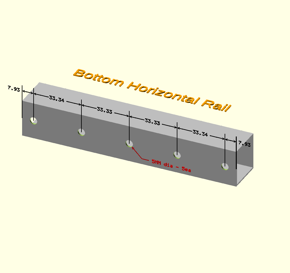
- Using a drill and a 5MM drill bit. Drill 5 each holes in each of the 4 rails (20 total). Drill pattern is below.
- Insert rivets using rivet gun. Do NOT insert the end rivets until the corner connectors are installed.


| Qty | Description |
|---|---|
| 4 | 1IN Aluminum Square Tube 149.2 MM long |
| 40 | 3MM threaded rivet insert |

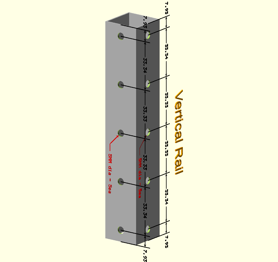
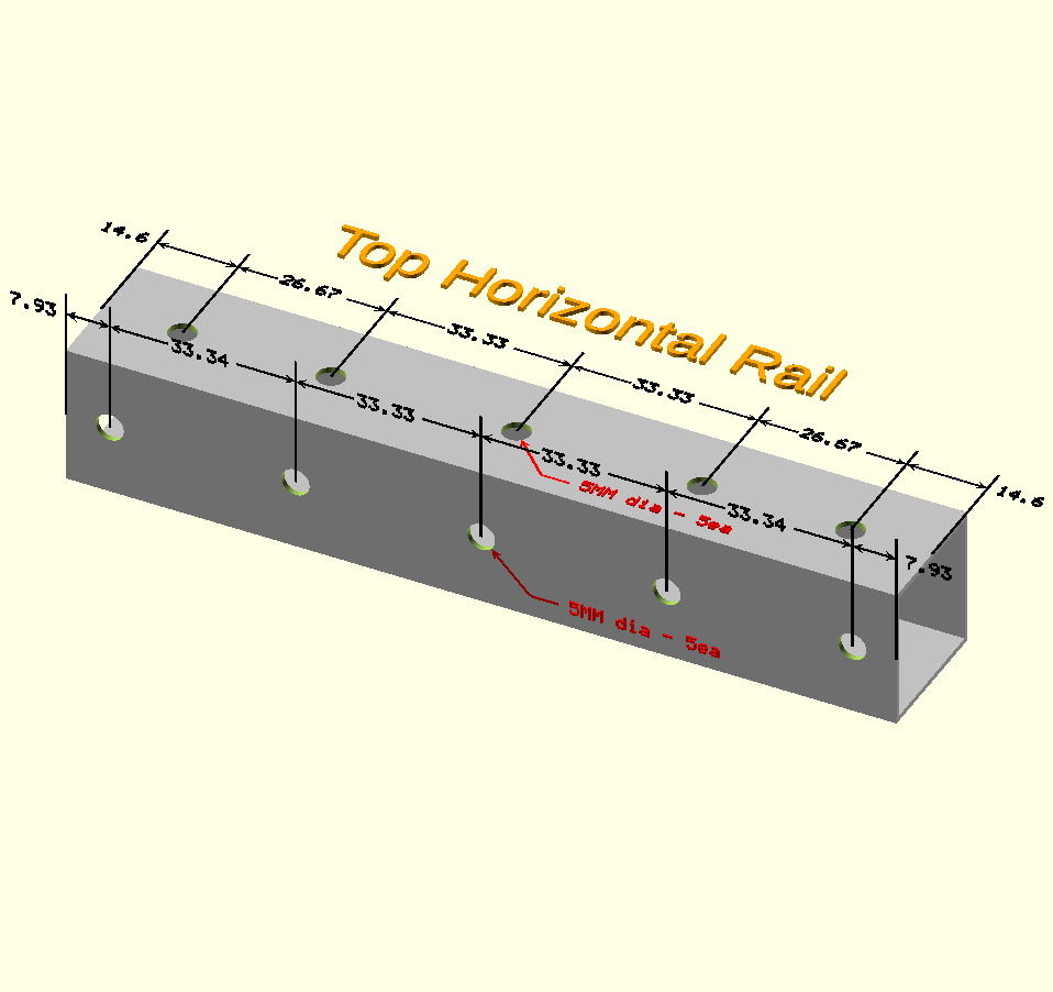
- Using a drill and a 5MM drill bit. Drill 10 each holes in each of the 4 rails (40 total). Drill pattern is below.
- Insert rivets using rivet gun. Do NOT insert the end rivets until the corner connectors are installed.


| Qty | Description |
|---|---|
| 4 | 1IN Aluminum Square Tube 149.2 MM long |
| 40 | 3MM threaded rivet insert |

- Using a drill and a 5MM drill bit. Drill 10 each holes in each of the 4 rails (40 total). Drill pattern is below.
- Insert rivets using rivet gun. Do NOT insert the end rivets until the corner connectors are installed.


| 4 x corner_tube_connector_bottom.stl |
|---|
 |
| 4 x corner_tube_top_assembly | 1 x frame_bottom_assembly | 1 x frame_middle_assembly |
|---|---|---|
|
|
|
| 1 x frame_top_assembly |
|---|
|


| Qty | Description |
|---|---|
| 2 | 3MM Armature wire - 5 inches long |
| 2 | Alligator Clip |
| 1 | Screw M3 cap x 16mm |
| 2 | Screw M3 cap x 12mm |
| 6 | Screw M3 cap x 8mm |
| 2 x armature_union.stl | 1 x din_rail_clip.stl | 1 x helping_hands_mount.stl |
|---|---|---|
 |
|
 |

- 3D print 2 each armature union, din rail clip, and helping hands mount See Print Settings
- Using a 3MM tap, tap the 4 holes of the armature unions.
- Using a 3MM tap, tap the 2 holes located on the face of the helping hands mount.
- Cut 2 each 5 inch sections of the 3MM armature wire.
- insert one side of the armature wire into the armature union and an alligator clip into the other end of the armature union and secure with the 8MM screws.
- Insert the other end of the 3MM armature wire into the helping hands mount and secure with a 8MM M3 screw.
- Use the 2 12MM M3 screws to secure the helping hands mount to the din rail clip.

| Qty | Description |
|---|---|
| 2 | 3M Dual lock velcro 149mm long |
| 1 | Magnifier Lamp Assembly |
| 2 | 3M Dual lock velcro 6mm long |
| 4 | 1 inch sq rubber foot |
| 1 x arduino_uno_mounting_plate_portrait_assembly | 1 x carry_handle_assembly | 4 x corner_lamp_holder_assembly |
|---|---|---|
|
 |
|
| 1 x din_rail_assembly | 1 x frame_assembly | 1 x helping_hands_assembly |
|---|---|---|
|
|
|
| 1 x power_strip_assembly | 1 x prop_assembly | 1 x raspberry_pi_mounting_plate_portrait_assembly |
|---|---|---|
|
 |
|
| 1 x small_breadboard_landscape_assembly | 1 x small_breadboard_portrait_assembly | 1 x tray_assembly |
|---|---|---|
|
|
|

- Cut 2 each 149mm sections of dual lock velcro.
- Remove dual lock backing and stick to the front and back inner bottom frame assembly. The power supply will stick to these velcro strips.
- Attach 4 each rubber feet to the bottom 4 corners of the cube.
- Cut 2 each 6mm sections of dual lock velcro.
- Attach these small strips of velcro to the left inner frame where the prop will go when it is stored inside the cube.
- Insert LED magnifying lamp into one of the 4 corner posts.
- Attach all other assemblies as indicated.
Top "# open-makers-cube"