[CIS565 2015F] Shadertoy: Morph
GLSL Ray Marching
University of Pennsylvania, CIS 565: GPU Programming and Architecture, Project 5
Terry Sun; Google Chrome 45.0, Arch Linux, Intel i5-4670, GTX 750
A ray-marching shader implemented as a fragment shader. For each pixel, a ray is shot from the camera into the scene. Rather than computing geometry intersections (as would be typical in a raytracer), this "marches" along the ray and, at each point, computes the distances away from objects defined in the scene. Objects are defined implicitly with signed data functions.
Live on Shadertoy!
The Shadertoy demo includes a large set of debug flags, where you can turn on:
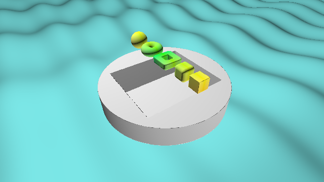
SCENE1/SCENE2: SCENE2 contains the image below; SCENE1 contains the geometry demoPLANE/HEIGHTMAP: enable or disable the (distance function-defined) plane below the scene or the height-mapped terrain (the two options toggled independently)FIXEDCAM: the camera rotates around the scene if 0OVERRELAX/SPEHRETRACE/NAIVE: for different raymarching typesDISTANCE/NORMAL/ITERS: for different debug displays
Check out the Shadertoy demo: there's animation!
Acknowledgements
This Shadertoy project uses code from the following resources:
- Morgan McGuire's Numerical Methods for Ray Tracing Implicitly Defined Surfaces. PDF
- Iñigo Quílez's Modeling with distance functions: Shadertoy
- Iñigo Quílez's Terrain Raymarching
- Iñigo Quílez's Free Penumbra Shadows for Raymarching Distance Fields (Soft shadows)
- Iñigo Quílez's [Menger fractal][menger]
And uses the following as resources only:
- "Enhanced Sphere Tracing." Keinert, Schafer, Korndorf, Ganse, Stamminger. PDF
Features
Technique
-
From the camera, shoot a ray into the scene. Then...
-
Naive raymarch: for every fixed-size step along a ray, compute the distance away from all objects in the scene. An object is considered intersected if it is below some small threshold.
-
Sphere tracing raymarch: at any given point along a ray, you have computed the minimum distance d from objects in the scene in order to check for intersections. Thus, if d doesn't indicate an intersection, it is safe to take a step of length d along the ray.
-
Terrain: If you have traveled some capped maximum distance away from the camera, consider the ray as not intersecting the scene. However, there is terrain! Continue the same raymarch, but compute terrain height rather than object distances. This must be a naive raymarch.
-
Shadows: Once the ray has intersected an object or terrain, initiate (yet another) raymarch from the point of intersection to the light. This will determine the shadowing factor at that point.
-
Lighting: Put the above together (intersection point, shadow factor) with a simple normal calculation for simple Lambert lighting.
Objects
Rererence: McGuire "Implicitly Defined Surfaces", iq "Modeling with distance functions", iq "Menger fractal"
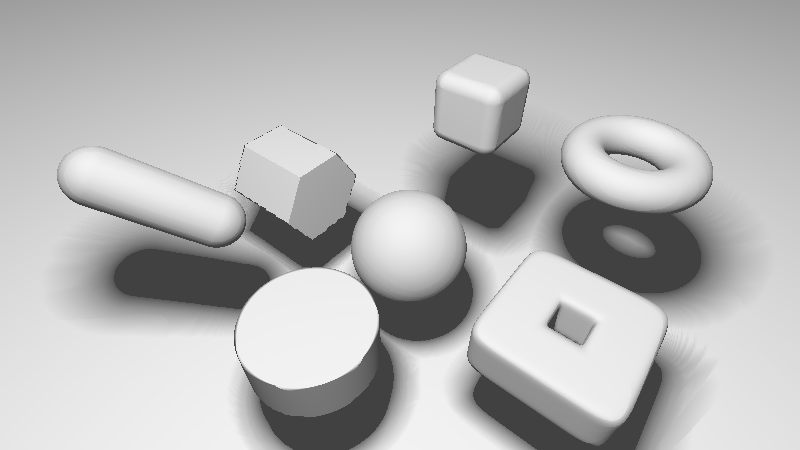
Geometries are defined implicitly with signed distance functions, mostly taken verbatim out of iq's references. Objects are composed with union and intersection functions.
Soft Shadows
Reference: iq "Modeling with distance functions", iq "Free Penumbra Shadows for Raymarching Distance Fields"
Compute a second raymarch from the intersection point to the light. Take the minimum over all points along the raymarch of the intersection distance against all objects in the scene. This yields soft shadows: even without a direct intersection, things that come close to intersection result in shadows.
Height Mapped Terrain
Reference: iq "Terrain Raymarching"
If a ray does not collide with any scene geometry after a max distance from the camera, instead compute an intersection with a terrain function. The terrain is defined with a function that takes an (x, z) pair and computes the height at that location.
For this raymarch we must use a naive method (with fixed step size), since the function does not compute a distance from a point on the ray to the terrain (it only defines the terrain height at a given point). That makes this technique very, very slow -- especially when the other two raymarches (initial object and soft shadow) can be optimized with sphere tracing.
Sphere Overrelaxation
Reference: McQuire "Implicitly Defined Surfaces", Keinert "Enhanced Sphere Tracing"
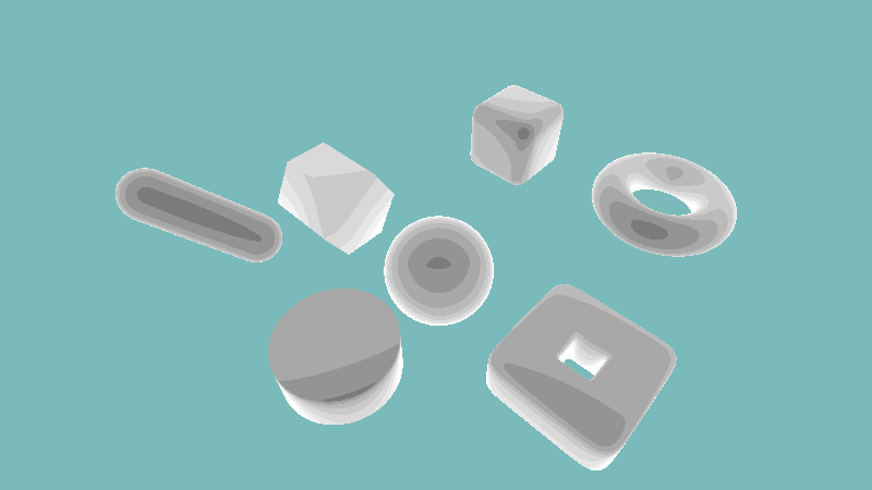
The number of ray march iterations displayed as grayscale, with darker areas indicating fewer iterations before the surface is considered intersected.
(This method is not currently working...)
Performance
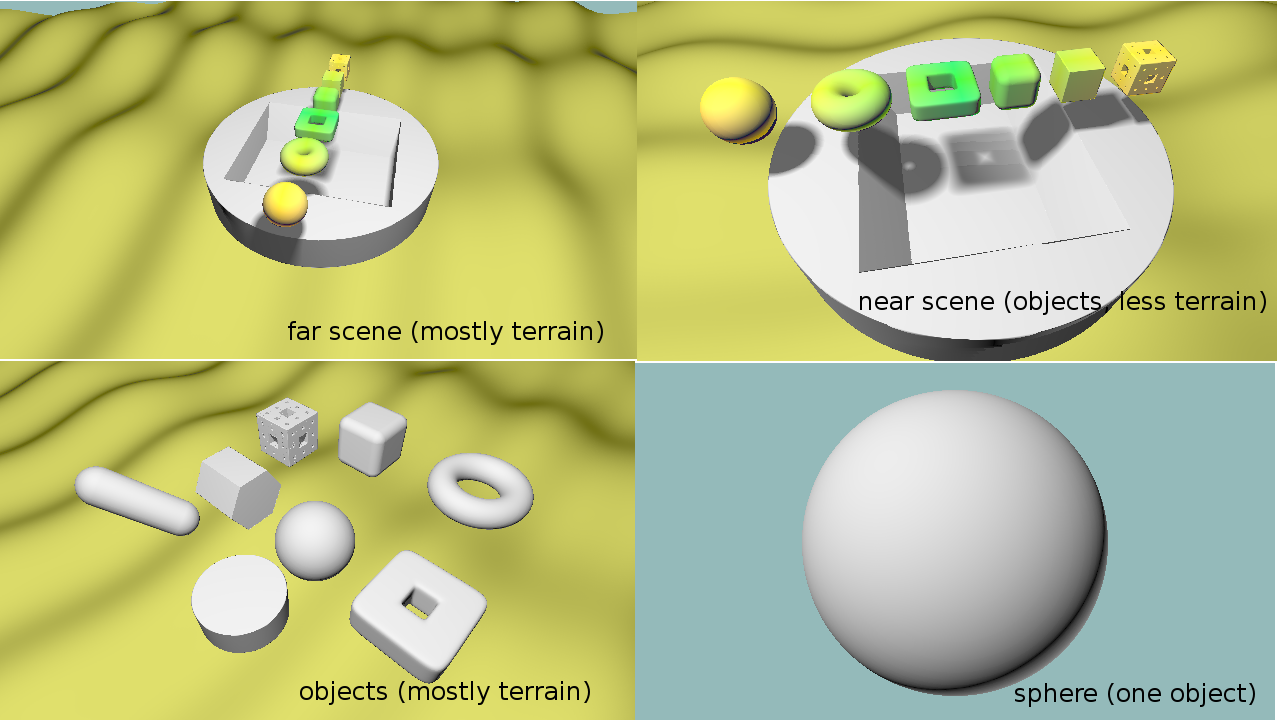
Performance data was taken from the following four scenes:
Data was taken with stats.js. Unfortunately it was hard to get a good reading by using the ms timer in statsjs, so I mostly relied on taking the FPS counter and calculating millisecond timing by 1000/FPS.
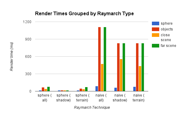
Render times for different scenes grouped by raymarch type:
Easy to see why naive raymarching is not done.
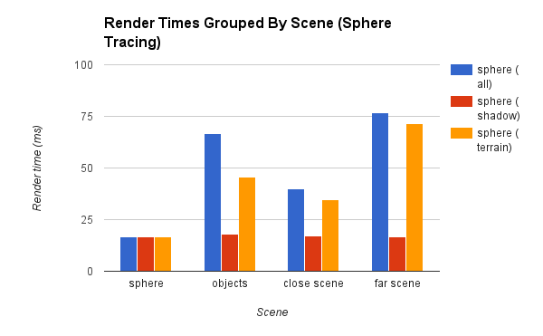
And the transpose, with only sphere tracing times:
Main takeaways:
-
Scenes where most of the rays intersect (early) are fast.
-
Terrain is very slow, because all rays which hit terrain did not intersect and had to complete a full raymarch, and additionally had to go through a second naive raymarch.
-
Shadows have a small effect. The shadow timing is really the difference between the all-scene and terrain-only scene. Reasonable: shadows should involve a (relatively short) raymarch capped at distance from intersection to light.
-
stats.js wasn't great for finding timing data: all of the shadow-only timings are actually bound by the 60fps cap. I intended to also take no-shadow/no-terrain data, but given this finding it would not have been very useful.
-
There sphere scene was similar to the close scene in composition, but had only one object rather than many. The difference in time between those two are likely due ot repeated distance function computations.
Another comparison I should have done would be a box and a menger sponge of the same size.
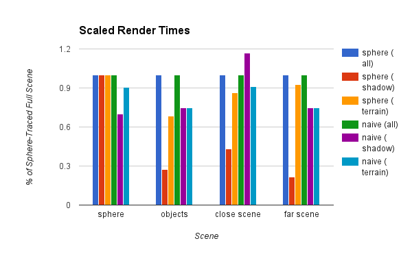
Since there's no use in directly comparing sphere-traced and naive times, this is a graph that scales render times by the full version of that raymarch type:
Bonus images
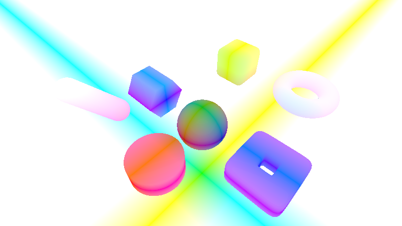
Raw position data, with the sphere at (0, 0, 0) and a plane underneath.
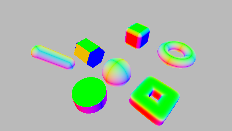
Normals for each geometry, computed with the equation given in McGuire (8).
Some geometry with iteration displayed as color (white indicates more raymarches before intersection).
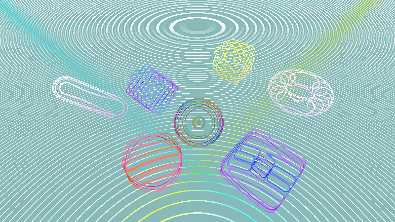
Naive ray marching with a step size of 0.1 (too large), got wireframes instead of solid shapes:
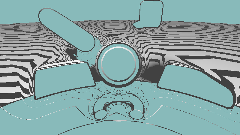
Overrelaxation without backwards step, resulting in stepping into the middle of the geometries (and gloopiness):

