This year, we are bulding a robot based on the Otto DIY kit. Today we will write simple programs to learn how each part can be controlled. Then we will fit everything together to make a complete system that walks without bumping into walls.
##I. Introduction 30 min Here are the building blocks of our robot:

This is a microcontroller, which will be used to give commands to the robot. You can think of a microcontroller as a very simple computer. For comparison, a smartphone is more than 100x faster than this microcontroller! However, it is more than powerful enough to make our robot walk and dance. This particular microcontroller is called an Arduino Nano. You can find out more about it here.
In order to control our robot, we will need to write a software program and send it to the Arduino. We use a program called an IDE (integrated development environment) to do this. We will download and install the IDE after we introduce all the main parts.
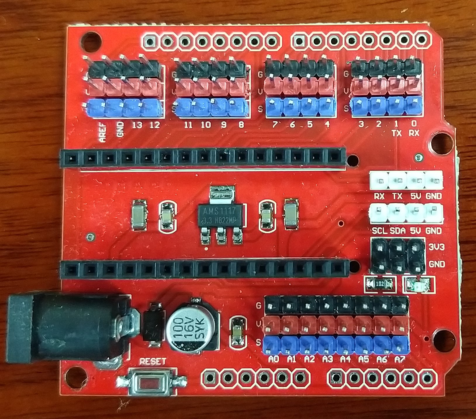
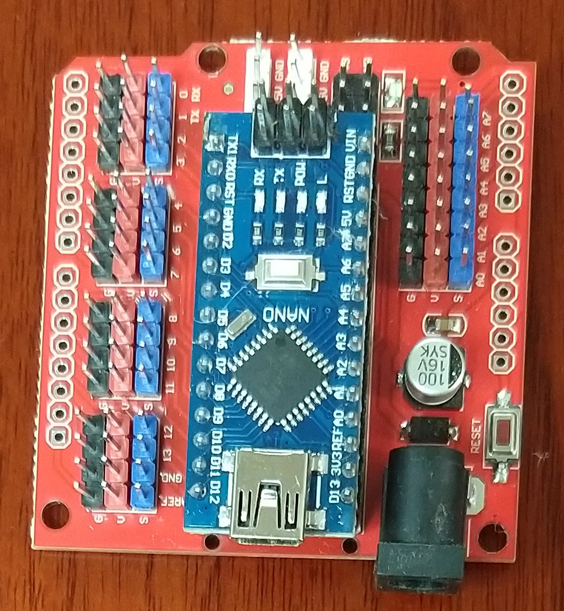
This is an add-on board for our Arduino Nano microcontroller, which makes it easier to connect other parts to the brain, similar to how our nervous system connects our muscles and sensory organs to our brains. This add-on board makes it easier to connect motors to make our robot move, and sensors to let our robot gather information about its surroundings.

This is a type of motor called a rotary servomotor. By controlling these, we can move our robot's body, similar to the way our muscles move our bodies. It has three wires: two are for power, and one is for sending special signals to control the motor. This motor can rotate to specific angles, based on the signals sent to it.
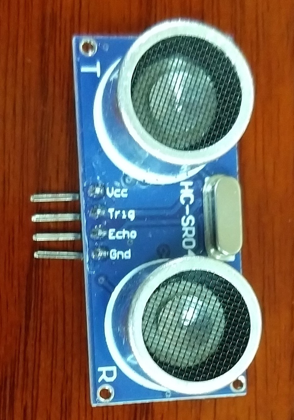
This is a distance sensor. It sends out ultrasonic sound waves from one side, then listens for echoes on the other side. Based on the time taken for the echo to arrive, it can estimate the distance to walls and other large objects in front of it. We will use this to make sure our robot does not keep walking when it gets to a wall.

Finally, we will build a cardboard body to hold all the parts together and make our robot move. The robot is made up of a head, legs, and feet.
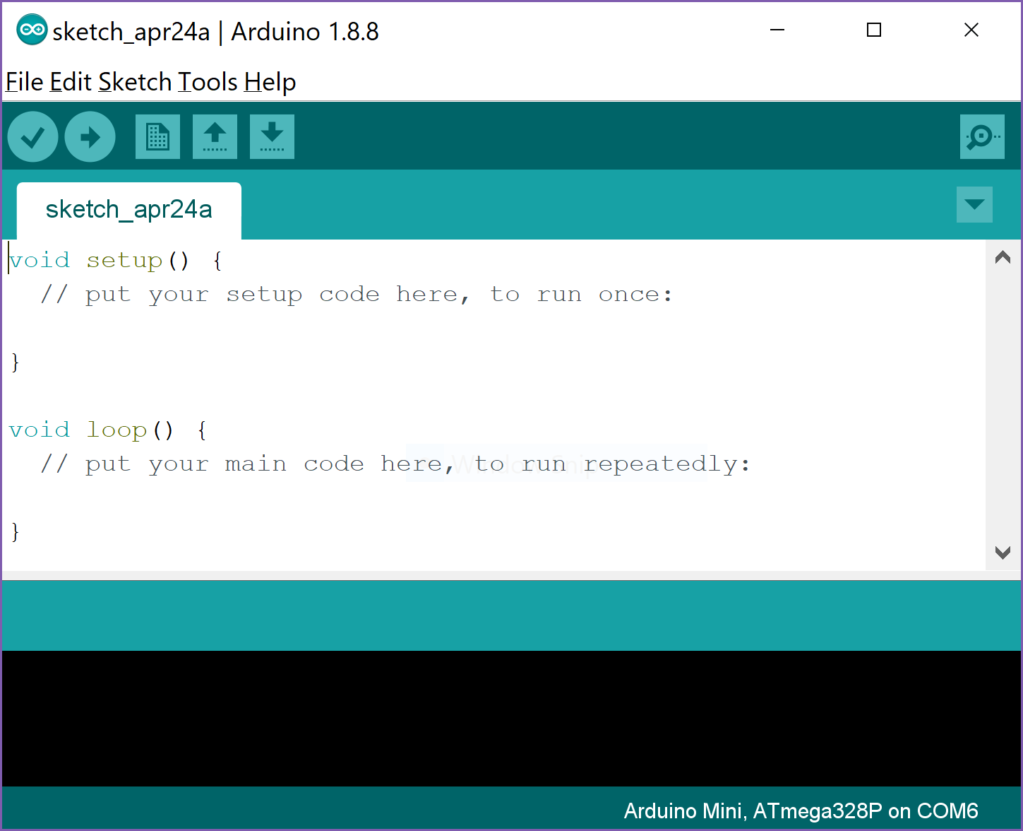
30 min To control our robot, we must be able to program the Arduino Nano microcontroller. First, we need to download the IDE from here. Download the zip file for 'non-admin install'. Extract it somewhere and double click on the Arduino.exe file. You will see something like the image below:
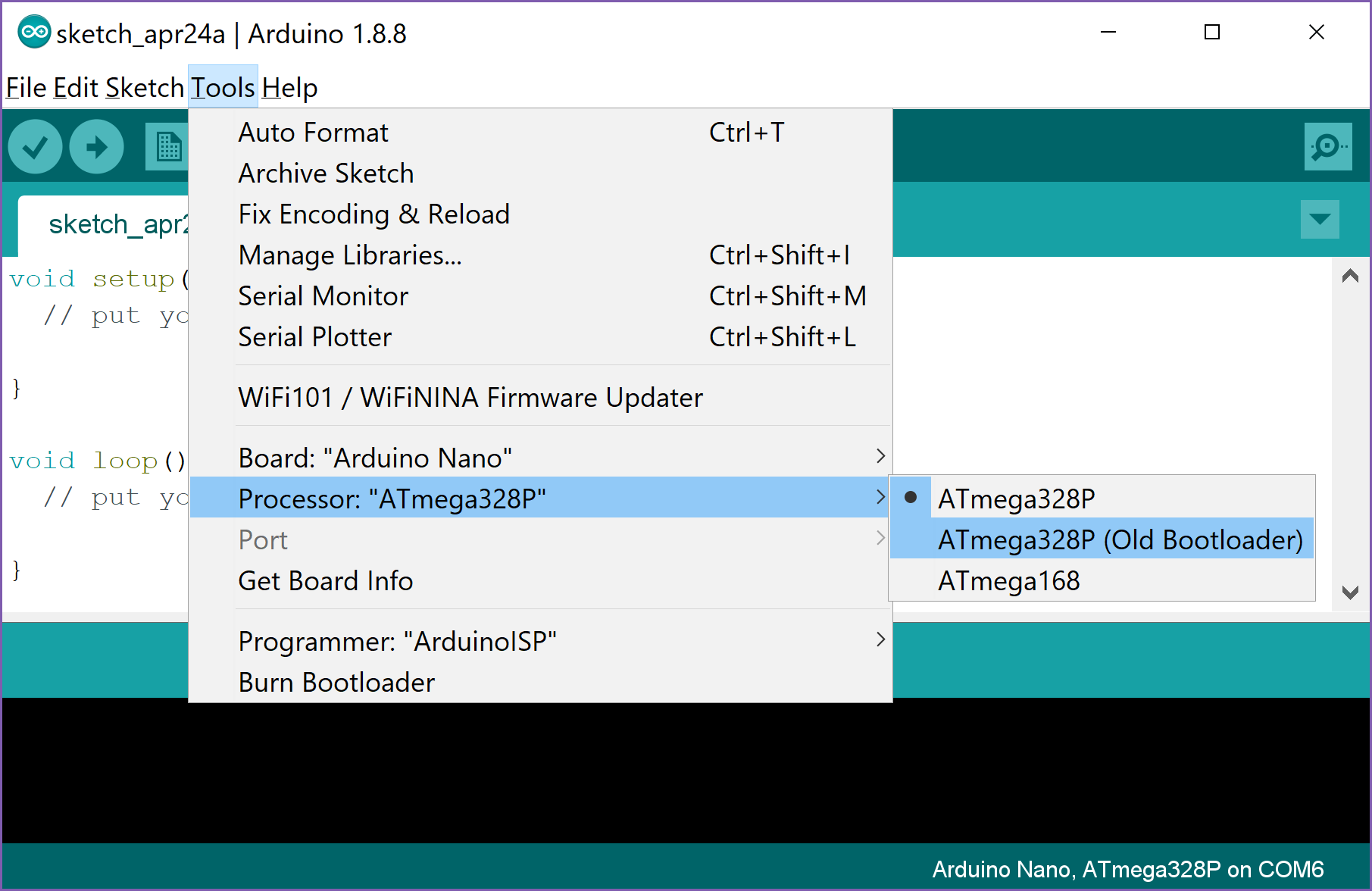
Then, plug one end of the USB cord into your Arduino Nano, and the other end to your computer. Red lights should turn on on the Arduino, showing that it is receiving power from the computer. Now we need to make sure the IDE knows what type of microcontroller we are using. Go to the Tools menu and look for the "Board" option. Select "Arduino Nano" from the list.

The boards we are using today need an additional step. Go to the Tools menu again, and change the "Processor" option to use the old bootloader.
Now we can send code to the Arduino. Before we continue, we will plug the Arduino into the socket on the driver board. Make sure to plug it in the correct way.
Finally, we need to download the Otto DIY libraries from Github. Click on the green button that says "Clone or download" then choose "Download ZIP". This will create a file called "DIY-master.zip" that contains important code to help us with our robot.
15 mins For our first examples, we will use a single motor and the distance sensor. The driver board contains many rows of three pins on each side. Each row contains black, red and blue pins. The black and red pins are called ground and power, respectively, and provide electric power to the components we want to attach. Each blue pin is connected to one of the pins on our Arduino Nano, so that signals can be transferred back and forth between the attached component and the microcontroller.
Unplug the Arduino from the USB cable, so that no power is flowing through it.
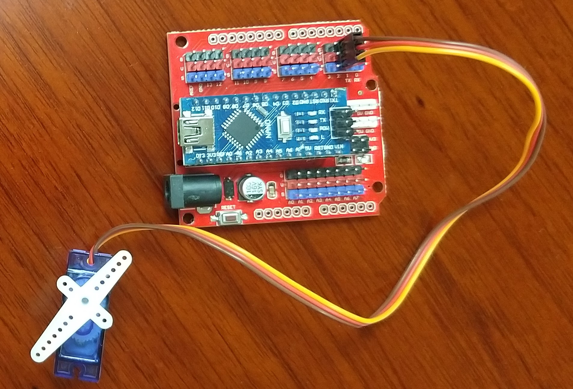
First, we will attach the servomotor. Look for the row of pins next to the number 2, and plug the motor wires into this row. Make sure that the brown wire is connected to the black pin (ground); that way, the other two pins will also be correctly attached. Then, take one of the plastic arms included with the motor and snap it on to the axle. This will let us see the rotation more clearly. Your connection should look like the image below.
Next, we attach the distance sensor. Take the bundle of 4 wires that is included with the sensor, and connect them so that the brown wire is attached to GND, and the yellow wire is attached to VCC. Using brown for ground keeps this sensor consistent with the motors, so we can easily see when something is connected incorrectly. Now we will connect the other end to the driver board. Connect the orange wire, TRIG, to blue pin 8, and connect the red wire, ECHO, to blue pin 9. Then connect the brown wire, GND, to any nearby black pin, and the yellow wire, VCC, to any nearby red pin. Check the image below to make sure you have connected everything correctly.

Now you are ready to try out some simple programming exercises.
The first thing we will do is try to control the servomotor. Connect the Arduino Nano to your computer. On your USB drive, you will see a file called "servo_example.ino". We will be modifying this file to learn how to control the motor. Double-click on the file, and the Arduino IDE will ask you to create a new directory for it. Agree, then click the "Upload" button to send the program to the micrcontroller.
Activity, 30min
Next, we will test the ultrasonic sensors. Open the "ultrasound_example.ino" file from your USB, the same way you did for the servo. Press the "Upload" button. There will be an error, because we need extra code to help us with the ultrasound sensor.
Go to the "DIY-master.zip" file and extract it. There is a folder called "libraries" inside. In your Arduino IDE, click on the "Sketch" menu, then go to "Include Library" and select "Add .ZIP library". Go into the "libraries" folder and look for "US". Add the US.zip file inside, and then click upload again. This time, there will be no error, but nothing will happen. We will use the serial monitor to get information from the Arduino as shown below.
Once you have the serial monitor running, you should see distance values from the sensors. Try putting your hand or other objects in front of the sensor to see it change.
Now that we have an input (distance sensor) and an output (servomotor), we can make more complicated programs. We can make the servomotor react to distance.
Activity, 45 min
1h 30min Now that we understand how the microcontroller connects all the components together, we can begin building the body of the robot. On your USB drive, there is a folder called "nets". Inside the folder are the measurements for all the body parts. Using your ruler, pencils and scissors, cut out each part. You should have one head, two legs, and two feet. The gray shaded areas indicate holes that need to be cut out. We will also need to punch a hole in each leg to connect to the body, holes in the foot to attach to the leg, and two holes in the head for the ultrasound sensor. Then we will attach the motors to the body. An example robot can be seen in the images folder on your USB drive.
We will leave the ultrasound connected as before, and connect the leg and foot servos as follows: Left leg: pin 2 Right leg: pin 3 Left foot: pin 4 Right foot: pin 5
Now we can play with our completed robot! As a test, go to the "DIY-master" folder, then to "Otto_run". Open the "Otto_run.ino" file inside and upload to your board. Your robot should begin to move forward without stopping or turning. Now, try changing the code so that the robot will stop when there is an obstacle in front of it.
Activity, 1h