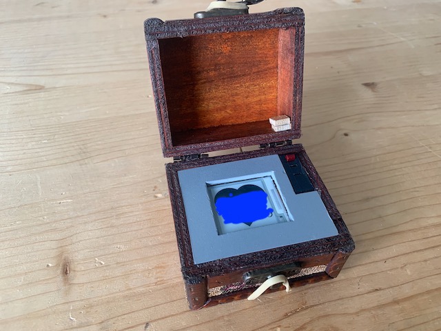
I wanted to make something truly unique for my girlfriend. As I love to do some electronics I started to look around for DIY gifts including electronics. I've seen some pages where people used 7 segment displays to count the number of days from or to an event. This is where I got my idea from.
Taka a small wooden box and put an ESP8266/ESP32 into it. Connect a battery and an e-Ink display to show the number of days since our first kiss. The only dev board with an integrated LiPo charge controller was an ESP32, so I used this one. Sadly the low-power modes were mostly useless as the board has way too many components and needs still 7.6mA when the ESP32 itself is in deep-sleep. To circumvent this issue I added a small toggle switch. Actually it is an end-switch for a 3D printer but it works. This switch disconnects the battery when the box is closed. As the box I've chosen does not stay open on itself, this should help to prevent draining the battery.
After some trial and error I found this sequence.
Box is closed. The battery is disconnected, ESP32 without power. E-Ink display show still old content (kinda splash-screen).
- Box gets opened
- Display shows splash screen while the ESP32 wakes up and reads the time from an RTC module.
- Display changes to some text and the number of days since our first kiss. In the background the ESP32 connects to the WiFi, uses NTP to get the current date/time and updates the RTC module.
- After some time, the display switches back to the splash screen. This is needed to make sure we do have a content which does not need updating. ESP32 goes into deep sleep.
- Box gets closed. Battery gets disconnected. E-Ink display still shows splash-screen, ready for the next time the box opens.
Using ESP32 deep sleep was not possible as the dev module drains way too much power. So the RTC module was added to make sure the ESP32 gets a time/date, even when WiFi is not (yet) connected or Box is outside of WiFi range.
If WiFi connects, NTP is used to update the RTC module to the correct date/time.
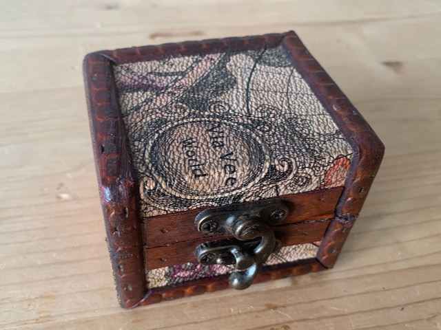
- Wooden box
- ESP32 dev board with LiPo charge circuit
- DS1307 RTC module with integrated battery
- Generic 200x200px e-Ink Display
- Small switch like for 3D printers end-stop
- LiPo battery (1S)
Just smash them together –seriously, it simply does not matter. Make sure you don't short anything. These are the pins I used.
| Part | Pin Part | Pin ESP32 |
|---|---|---|
| e-Ink Display | Busy | 4 |
| e-Ink Display | RST | 16 |
| e-Ink Display | CS | 17 |
| e-Ink Display | CS | 5 (SS) |
| e-Ink Display | CLK | 18 (SCK) |
| e-Ink Display | DIN | 23 (MOSI) |
| RTC module | SDA | 25 |
| RTC module | SCL | 26 |
And make sure to connect Vcc and Gnd for all the parts.
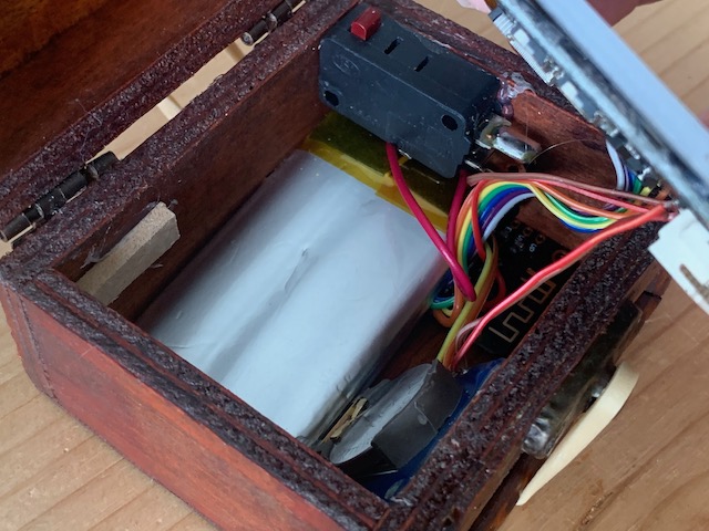
Battery Ground wire is split up and switch added. Make sure the battery is connected then the box is open (switch NOT pressed).
That's it. Mount it in a box (I used quite a bit of hot glue) and make sure you can still access the USB port as this is needed to flash other firmware and also to charge the battery.
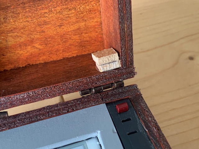
I added a bit of wood to make sure the switch is pushed when the box closes. Works fine…
My ESP32 dev module does not have a battery voltage sense pin. So it is not possible to read out the voltage and show a message on screen.


