USBJWA (USB Joystick Web App) turns a tablet or any device with a Web browser into a USB joystick. Anyone having difficulties using a regular joystick may find a touch joystick easier to use.
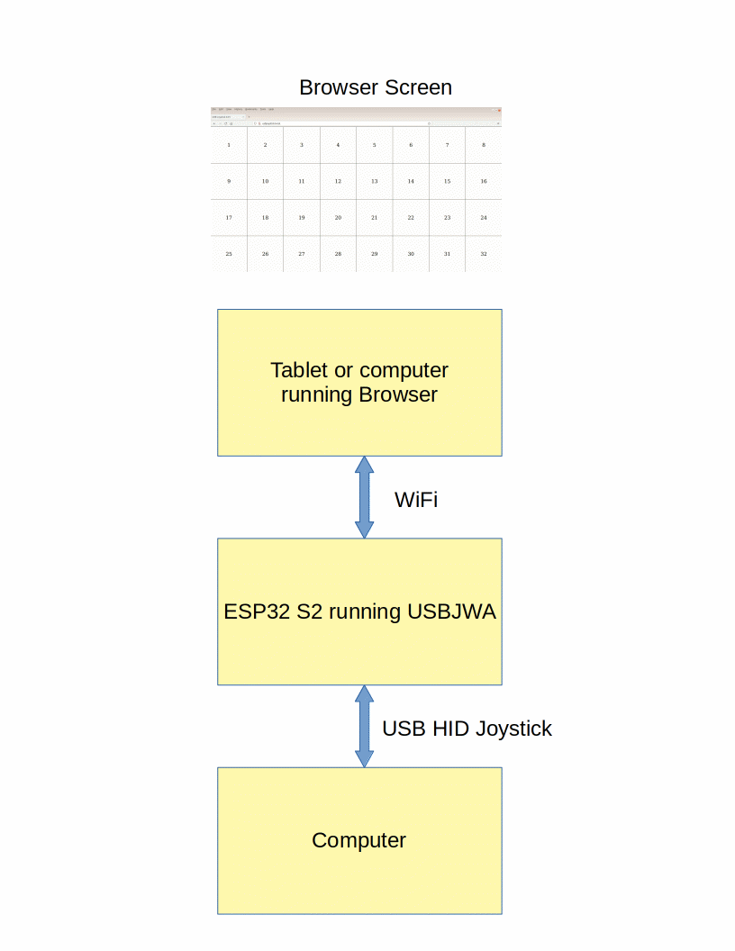
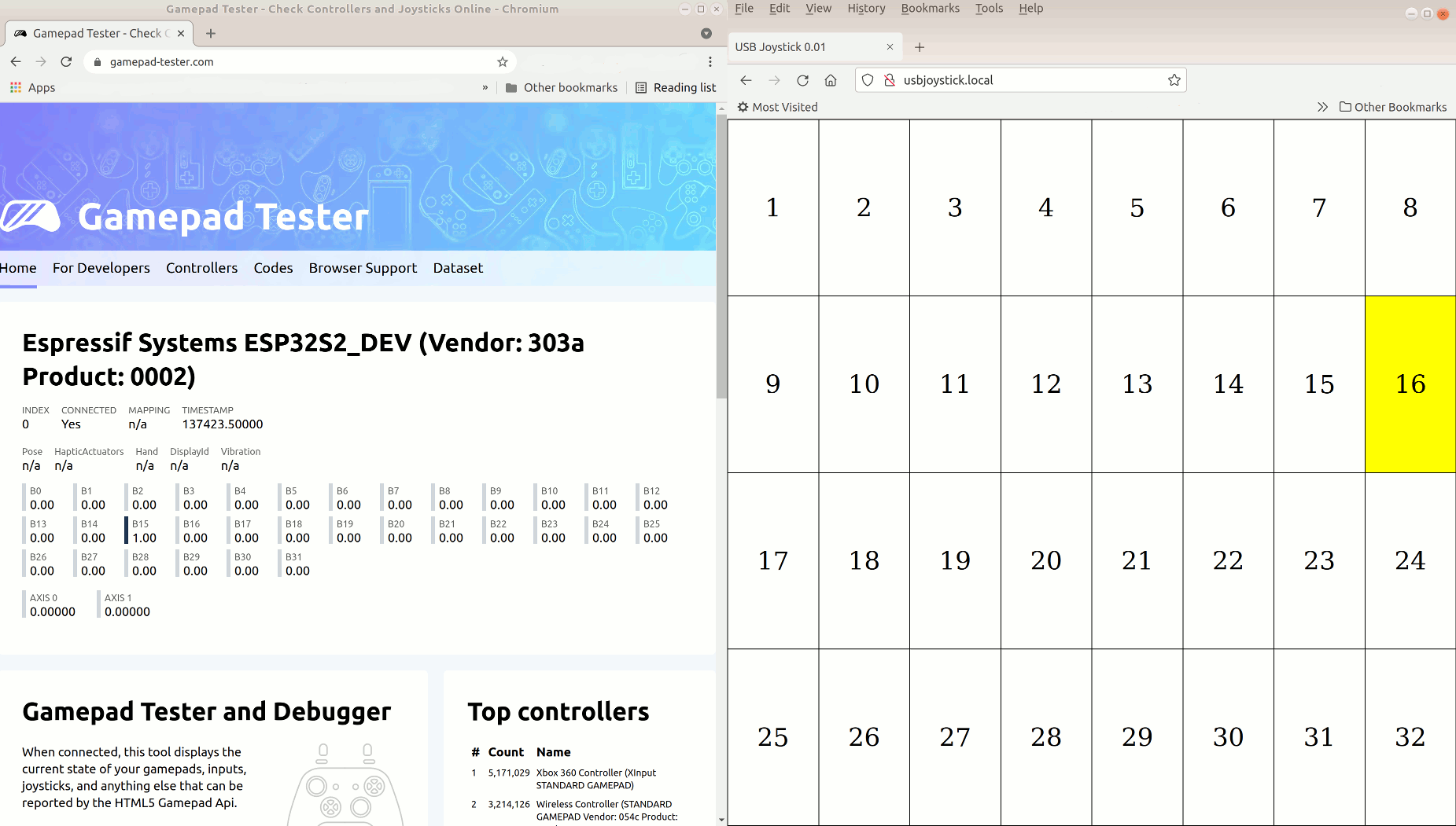
The joystick web app displays a 4x8 grid in the browser window. The locations of touch or mouse events are sent via a web socket back to the ESP32 S2 web server. The server translates locations to USB HID joystick buttons and sends them out the USB HID joystick interface.
The ESP32 S2 Saola board is programmed using the Arduino IDE. No soldering is required. The browser communicates to the ESP32 S2 using WiFi. The ESP32 S2 communicates with the other computer using USB HID.
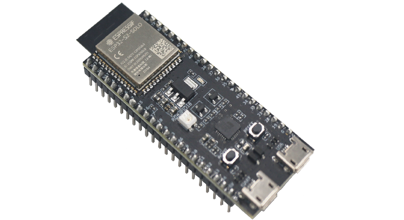
This should work on any ESP32 S2 board but has only been tested on the Espressif Saola and DevKitC boards. Regular ESP32 boards do not have native USB hardware so will not work.
The ESP32 S2 DevKitC includes a connector for the USB interface as well as the UART interface. No wires or extra connectors are required.
On the Saola board, the USB micro connector is connected to a CP2102 USB Serial chip. The USB data is on pin 19 and 20. A separate USB connector or cable must be connected to pins 19, 20, GND, and 5V. Do not use both connectors at the same time. If there is no protection diode on the 5V pin, board may be damaged. Connect to the built-in USB micro connector to program the ESP32 S2. Disconnect the cable then plug it into the other USB micro connector to test the USB feature.
| ESP32 S2 Saola | USB micro connector |
|---|---|
| GND | GND |
| 5V | VBUS |
| 19 (USB D-) | D- |
| 20 (USB D+) | D+ |
| not connected | ID |
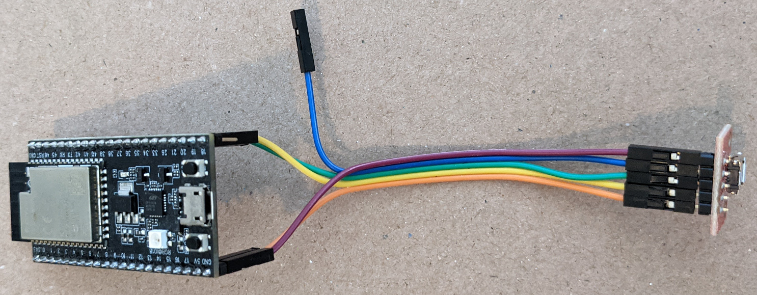
In the following photo, the USB connector is a SparkFun micro USB breakout board connected to the ESP32 S2 Saola board using Dupont wires.
The ADC1 inputs inputs are reserved for capacitive touch so the joystick X,Y outputs are connected to ADC2 analog inputs.
| Pin | Label | Function | Joystick |
|---|---|---|---|
| 17 | 15 | GPIO15, ADC2_CH4 | Xout arduino(A14) |
| 18 | 16 | GPIO16, ADC2_CH5 | Yout arduino(A15) |
| 19 | 17 | GPIO17, INPUT_PULL | Sel |
| 1 | 3V3 | 3.3V power | 2.5V (see below for divider) |
| 42 | GND | Ground | GND |
https://docs.espressif.com/projects/esp-idf/en/latest/esp32s2/api-reference/peripherals/adc.html
Note: The maximum input value to an analog input pin is 2.5V. A 3.3K Ohm resistor is used to divide the 3.3 voltage.
3.3V
  |
3.3K Ohm resistor
  |
  o-- Joystick VCC
  |
 10K Ohm joystick pot
  |
  Gnd

2.5V(Vout) = 3.3V(Vin) * 10K Ohm / (3.3K + 10K Ohm)
The following libraries can be installed using the IDE Library Manager.


