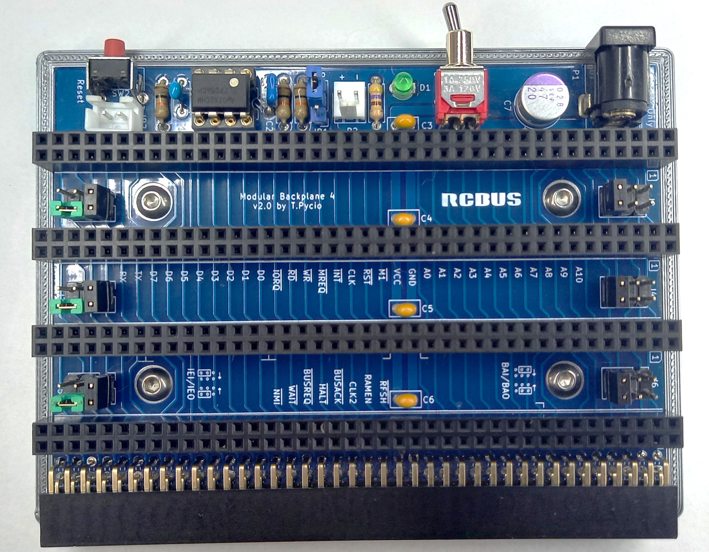
Backplane 4+1 for RCBus
| Position | Description |
|---|---|
| 1-2 | enable |
| 2-3 | disable |
| Component type | Reference | Description | Quantity |
|---|---|---|---|
| PCB | Backplane4 PCB - Version 2.0 | 1 | |
| Integrated Circuit | U1 | TL7705A - 5-V supervisor, 8 pin DIP | 1 |
| LED | D1 | LED indicator, 3mm | 1 |
| Switch | SW1 | Switch ON-ON, TSSM1022C3, SMTS-102C3 | 1 |
| Button | SW2 | 6x6 Right Angle Tactile Push Button | 1 |
| Resistor | R1 - R3 | 10 kohm, 0.25 W, axial | 3 |
| Resistor | R4 | 470 ohm, 0.25 W, axial | 1 |
| Capacitor | C1 | 10 nF, 50V, MLCC, 5 mm pitch | 1 |
| Capacitor | C2 | 0.1 uF, 50V, MLCC, 5 mm pitch | 1 |
| Capacitor | C3 - C6 | 0.1 uF, 50V, MLCC, 2.5 mm pitch | 4 |
| Capacitor | C7 | 47 uF, 10V, electrolytic, 3.8 mm pitch | 1 |
| DC Supply | P1 | DC supply socket, male, soldering, 5.5/2.1 | 1 |
| Power Socket | P2 | Socket, wire-board, male, 2.45 mm pitch | 1 |
| Connector | S1 - S4 | Pin strips, 2x40 female, straight, 2.54mm | 4 |
| Connector | S5 | Pin strips, 2x40 female, angled 90°, 2.54mm | 1 |
| Pin Header | J1 - J6 | 2x2 pin header, 2.54 mm pitch | 6 |
| Pin Header | JP1 | 1x3 pin header, 2.54 mm pitch | 1 |
| Connector | JP2 | 2 pin JST XH2.54 socket male | 1 |
Gerber files prepared for production at JLCPCB
Mounting plate base for 3D printing
Copyright 2024 Tadeusz Pycio
This work is licensed under a Creative Commons Attribution-NonCommercial 4.0 International (CC BY-NC 4.0) .
