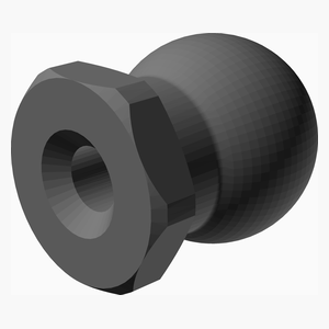
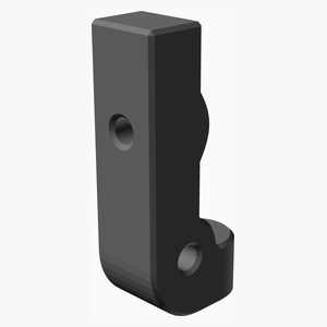
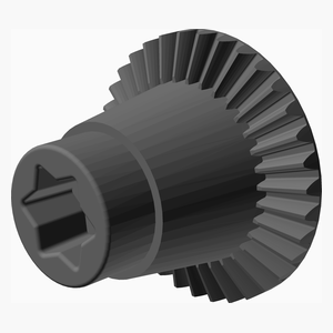
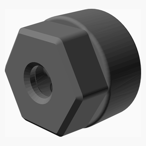
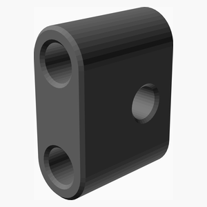
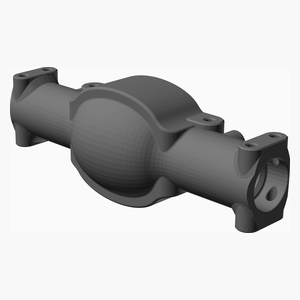
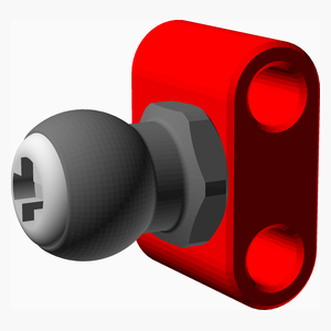
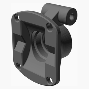
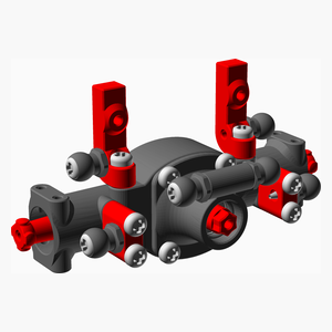
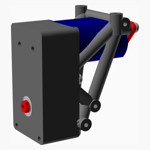
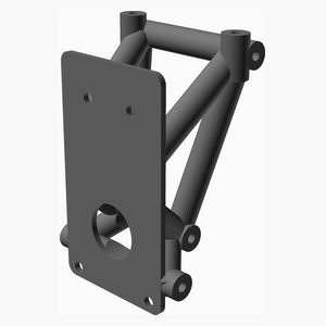
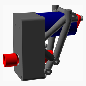
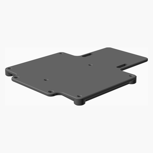
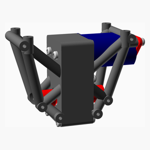
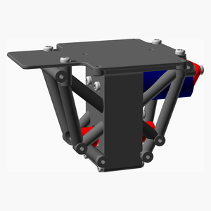
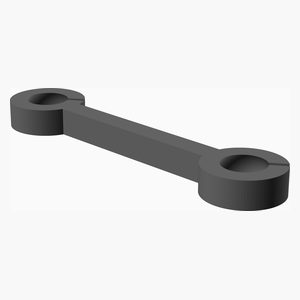
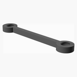
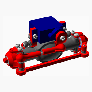
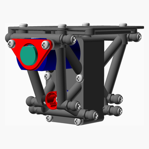
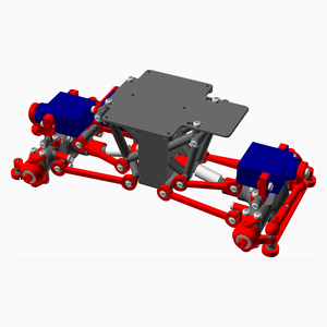
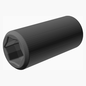
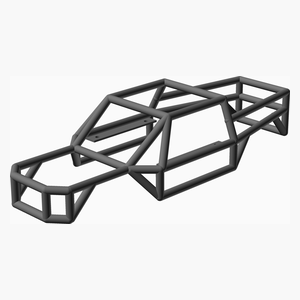
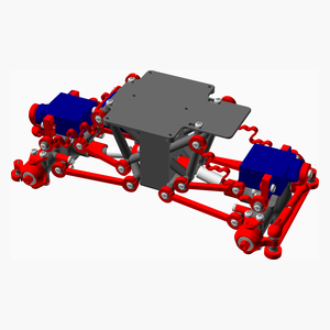
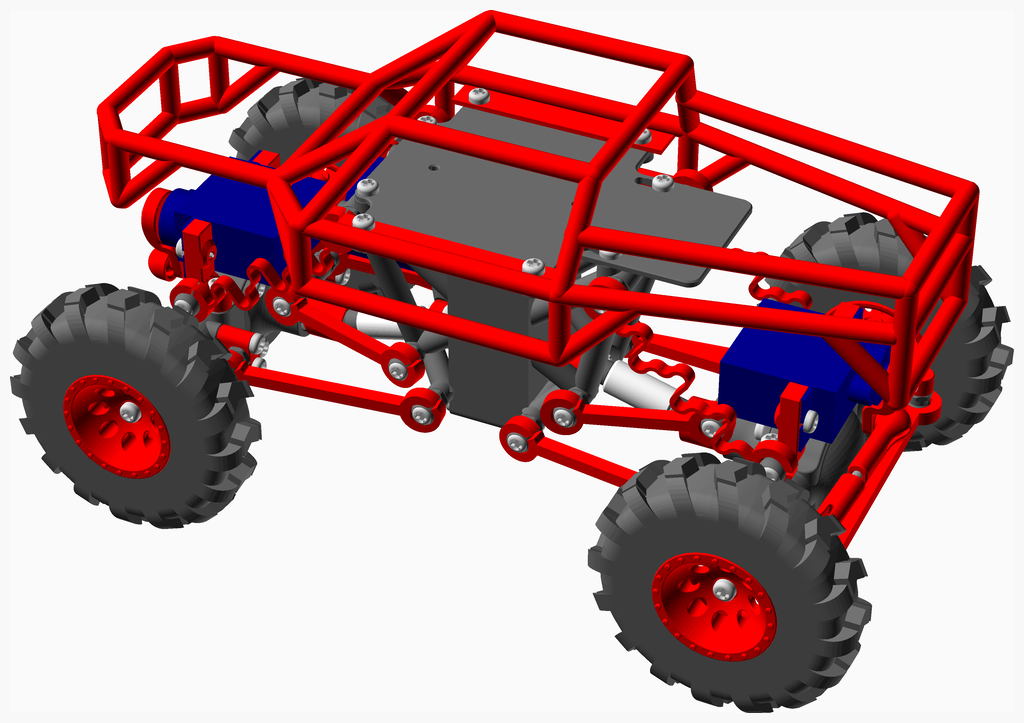
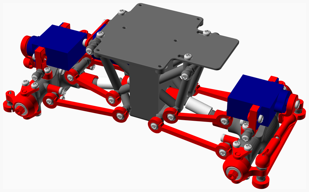
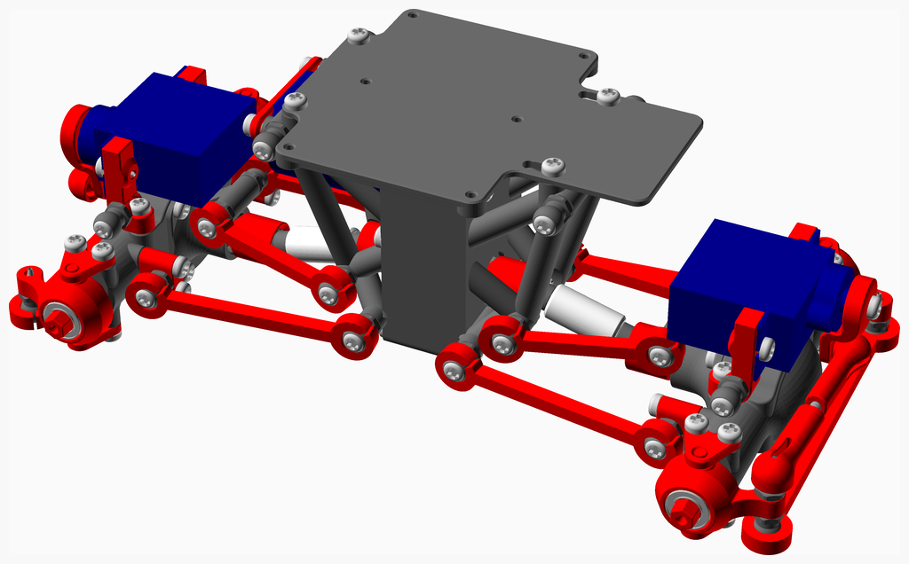
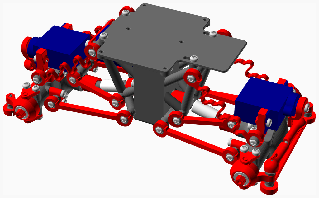
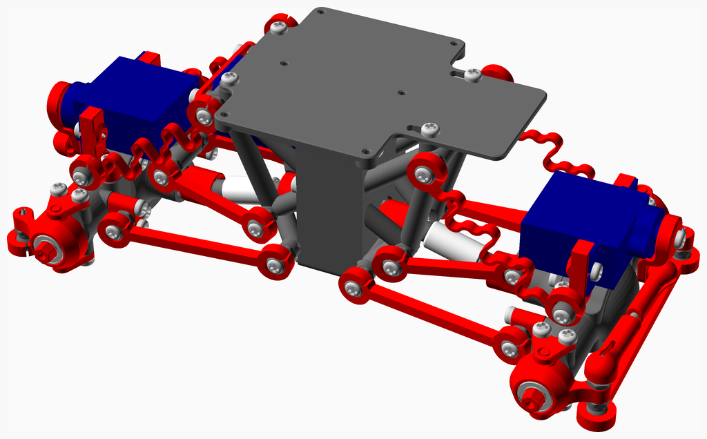
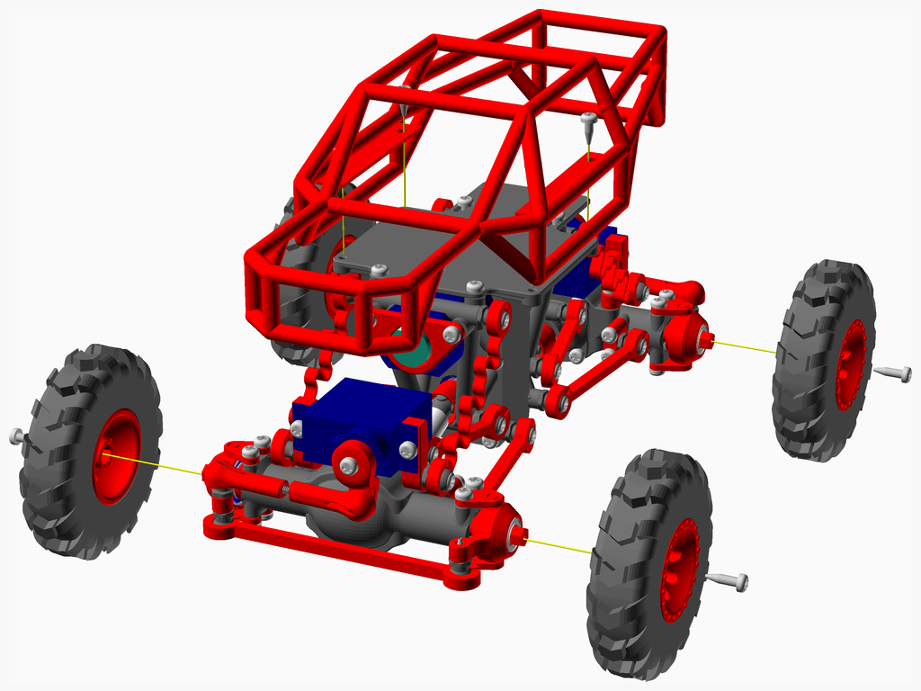
This is a remix version of an RC Rock Crawler that I found on Thingiverse.
The original model got deleted since then. So I included the original here.
The remix was first publish in Thingiverse at Remix Rc Rock Crawler, new gearbox .
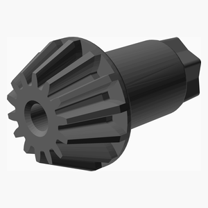
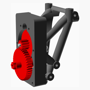
I modified the gearbox to make it slower, hence with more torque.
General instruction:
Make sure the printer is well calibrated. Specifically the extruder. The extrusion factor, also know as the extrusion multiplier, will have a big impact on the way the pieces fits together. I personnaly use that guide before using a new filament: Extrusion Multiplier
Print every pieces in PLA.
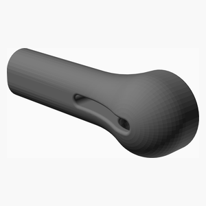
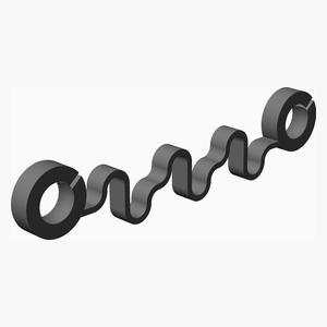
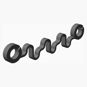
Print the shock in PETG to get more flexibility.
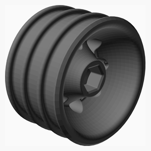
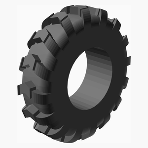
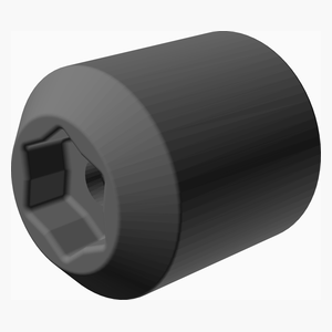
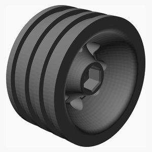
If you decide to print the tires print them in TPU, the softest one you can find. The grip is not very good with printed tires. For better grip you can buy the tires. In that case print the wheel part wheel_26_5mm.stl.
If the screws tend to break the plastic part you can enlarge the hole with a drill bit.
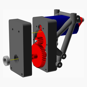
Use plenty of light grease in the gear box
Use a bit of light grease in the wheel hub.
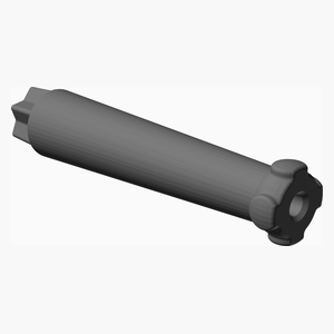
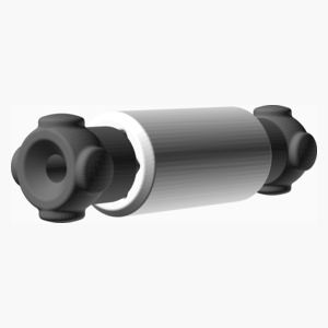
If the center drive shaft keep falling off you can print this longer one: Center_Drive_Shaft_P2_15.55mm.stl.
I provided a longer shock shock_46mm_stl. The short version tend to keep the car a bit low.
Video:
In action Showing the shock Gearbox assembly
I found a link to the original video from the original designer:
Make an RC Rock Crawler - Part 1 Make an RC Rock Crawler - Part 2
Documentation generated by the OpenSCAD library NopSCADlib .
License: Creative Commons - Attribution - Share Alike .
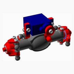
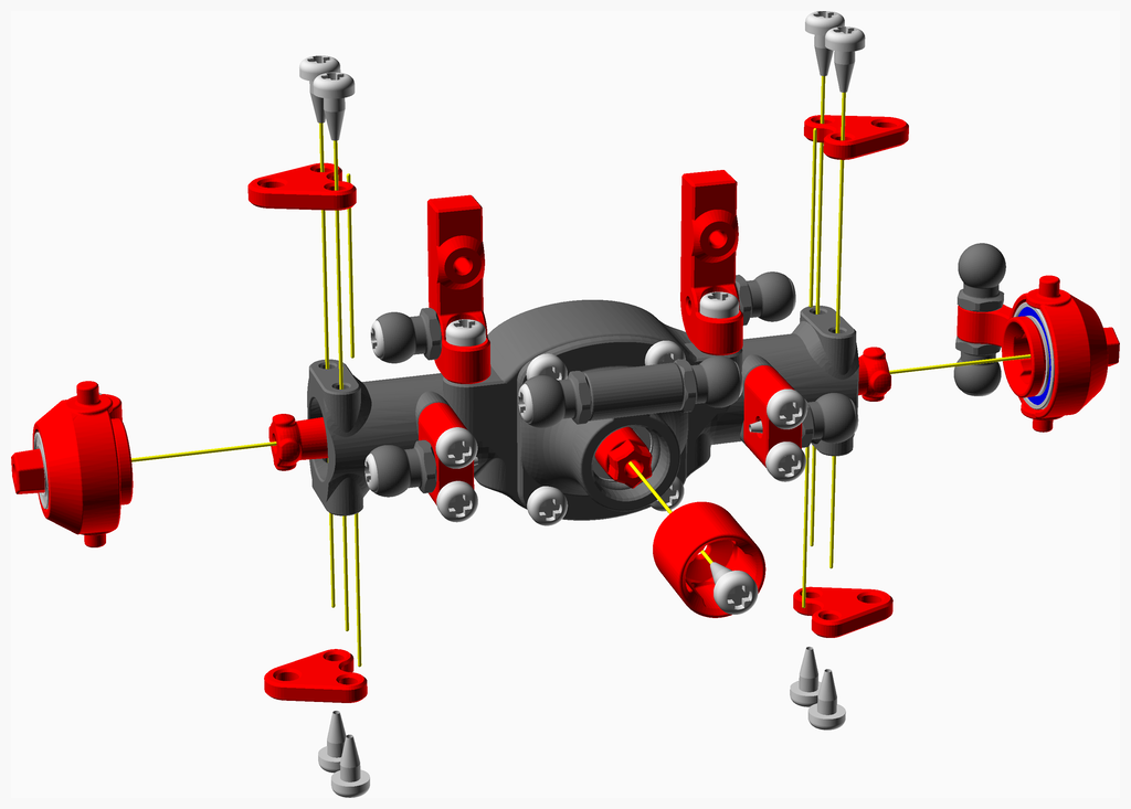
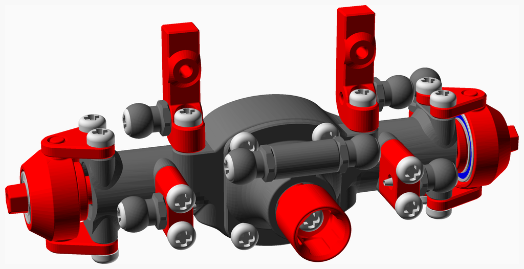
Parts list Wheel Left Assembly Wheel Right Assembly Drive Shaft Assembly Servo Control Link Assembly Hub R Assembly Hub L Assembly Axle Part1 1 R Assembly Axle Part1 1 L Assembly G34 Assembly Axle Part1 Assembly Axle Part2 Assembly Axle Part3 Assembly Axle Part4 Assembly Axle Part5 Assembly Axle Part6 Assembly Axle Part7 Assembly Axle Final Assembly GearBox Part1 Assembly GearBox Part2 Assembly GearBox Part3 Assembly GearBox Part4 Assembly GearBox Part5 Assembly GearBox Part6 Assembly GearBox Part7 Assembly GearBox Final Assembly Suspension Part1 Assembly Suspension Part2 Assembly Main Assembly
Top
2 x Axle Final GearBox Final Main TOTALS
Vitamins
8
.
.
8
Ball bearing MR128-2RS 8mm x 12mm x 3.5mm
6
2
.
8
Ball bearing MR63ZZ 5mm x 8mm x 2.5mm
16
4
.
20
Screw M2 pan self tap x 5mm
18
8
4
30
Screw M2 pan self tap x 6mm
4
.
4
8
Screw M2 pan self tap x 8mm
14
12
.
26
Screw M2 pan self tap x 10mm
10
4
.
14
Screw M2 pan self tap x 12mm
.
1
.
1
Smooth rod 2mm x 10mm
2
.
.
2
Threaded rod M2 x 10mm
2
.
.
2
RC servo SG90
.
1
.
1
motor 130, 6 volts
80
32
8
120
Total vitamins count
3D printed parts
2
.
.
2
5_5_ball_Closed.stl
16
12
.
28
5_5_ball_Open.stl
2
.
.
2
Axle_Case_p1.stl
2
.
.
2
Axle_Case_p2.stl
8
.
.
8
Axle_Case_p3.stl
4
.
.
4
Axle_Case_p4.stl
.
.
4
4
Ball_Link_29mm.stl
.
.
4
4
Ball_Link_41mm.stl
2
.
.
2
Ball_Link_62mm.stl
2
2
.
4
Center_Drive_Cup.stl
.
.
4
4
Center_Drive_Shaft_P1.stl
.
.
2
2
Center_Drive_Shaft_P2.stl
.
.
1
1
Center_Drive_Shaft_P2_15_5mm.stl
4
.
.
4
Drive_Cup.stl
4
.
.
4
Drive_Shaft.stl
2
.
.
2
G34_P14_p1.stl
2
.
.
2
G34_P14_p2.stl
4
.
.
4
Hub.stl
4
.
.
4
Link_Closed_35mm.stl
.
1
.
1
Motor_Holder.stl
2
.
.
2
P14_G34.stl
4
.
.
4
Servo_Holder.stl
2
.
.
2
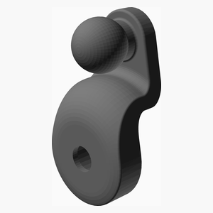
Servo_Horn.stl
.
.
4
4
Wheel.stl
.
.
1
1
body_v3.stl
.
1
.
1
firstStageGear.stl
.
1
.
1
frameBack_v2_1.stl
.
1
.
1
frameFront_v2_1.stl
.
1
.
1
gearMotor.stl
.
1
.
1
gearboxBack_v2.stl
.
1
.
1
gearboxFront_v2.stl
.
1
.
1
plate_long_v2.stl
.
1
.
1
secondStageGear.stl
.
.
4
4
shock_43mm.stl
.
.
1
1
shock_46mm.stl
.
.
4
4
tire_v3.stl
.
.
1
1
wheel_26_5mm.stl
66
23
30
119
Total 3D printed parts count
Top
2 x Wheel.stl
2 x tire_v3.stl
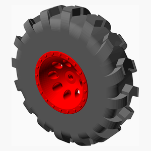
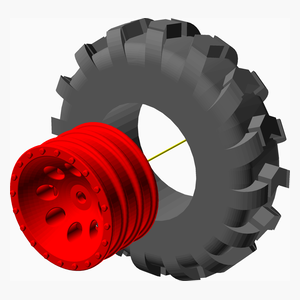
Install the tire on the rim
Top
2 x Wheel.stl
2 x tire_v3.stl
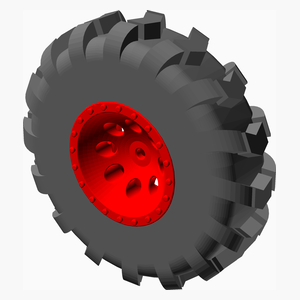
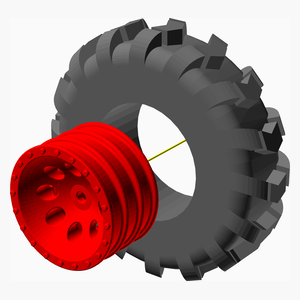
Install the tire on the rim the thread oriented the other way compare to the wheel_left_assembly.
Top
4 x Center_Drive_Shaft_P1.stl
2 x Center_Drive_Shaft_P2.stl
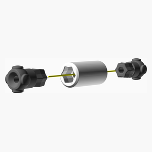
It is a good idea to print the Center_Drive_Shaft_P2 in TPU. It makes the assembly a bit easier
Press fix both Center_Drive_Shaft_P1 into Center_Drive_Shaft_P2.
Top
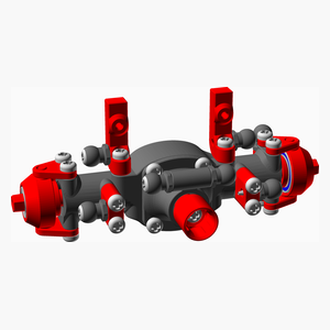
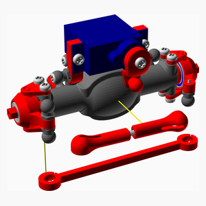
2 x Servo Control Link Assembly
Qty
Description
2
Threaded rod M2 x 10mm
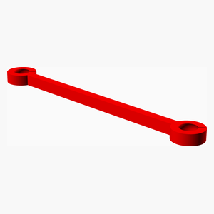
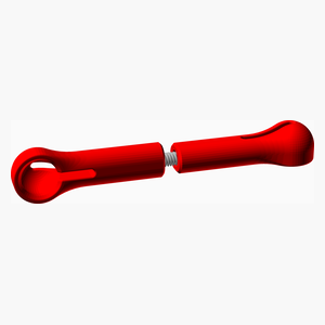
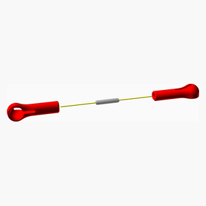
4 x Link_Closed_35mm.stl
Screw both Link_Closed_35mm on a 10 mm M2 threaded rod. Leave a gap of about 1 or 2 mm in the middle.
Top
Qty
Description
2
Ball bearing MR128-2RS 8mm x 12mm x 3.5mm
2
Ball bearing MR63ZZ 5mm x 8mm x 2.5mm
2
Screw M2 pan self tap x 10mm
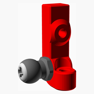
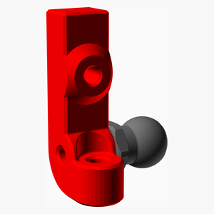
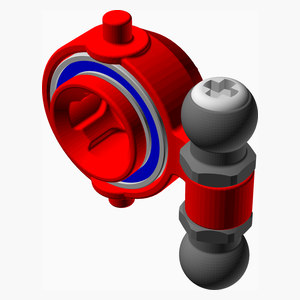
2 x 5_5_ball_Open.stl
2 x Drive_Cup.stl
2 x Hub.stl
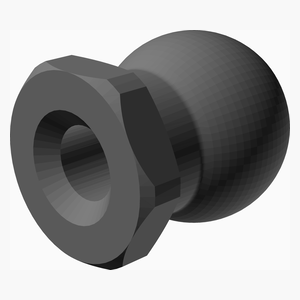
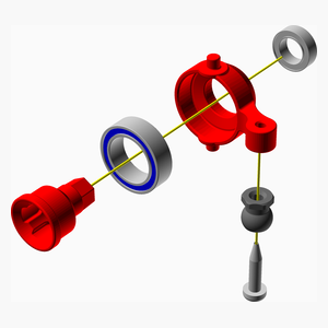
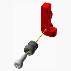
Install a 5_5_ball_Open with a M2 self tapping screw 10 mm.
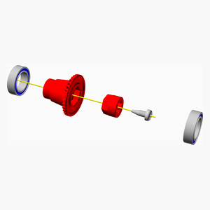
Install a bearing MR128 in the hub.
Install a bearing MR63 in the hub.
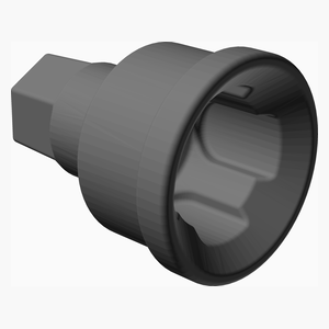
Install a Drive_Cup in the hub.
Top
Qty
Description
2
Ball bearing MR128-2RS 8mm x 12mm x 3.5mm
2
Ball bearing MR63ZZ 5mm x 8mm x 2.5mm
2
Screw M2 pan self tap x 12mm
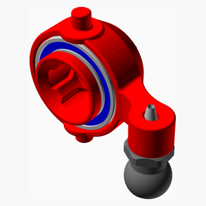
2 x 5_5_ball_Closed.stl
2 x 5_5_ball_Open.stl
2 x Drive_Cup.stl
2 x Hub.stl
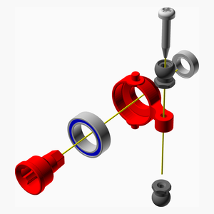
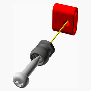
Crew together a 5_5_ball_Open and a 5_5_ball_Closed with a M2 self tapping screw 12 mm.
Install a bearing MR128 in the Hub.
Install a bearing MR63 in the Hub.
Install a Drive_Cup in the Hub.
Top
2 x Axle Part1 1 R Assembly
Qty
Description
2
Screw M2 pan self tap x 8mm
2 x 5_5_ball_Open.stl
2 x Servo_Holder.stl
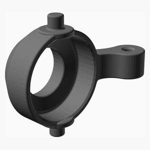
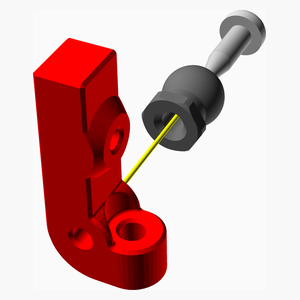
Install a 5_5_ball_Closed on right side of a Servo_Holder using a M2 self tapping screw 8 mm.
Top
2 x Axle Part1 1 L Assembly
Qty
Description
2
Screw M2 pan self tap x 8mm
2 x 5_5_ball_Open.stl
2 x Servo_Holder.stl
Install a 5_5_ball_Closed on left side of a Servo_Holder using a M2 self tapping screw 8 mm.
Top
Qty
Description
4
Ball bearing MR128-2RS 8mm x 12mm x 3.5mm
2
Screw M2 pan self tap x 6mm
2 x G34_P14_p1.stl
2 x G34_P14_p2.stl
Insert G34_P14_p2 in G34_P14_p1 using a M2 self tapping screw 8 mm.
Add the ball bearing MR128 at both ends.
Top
Qty
Description
4
Screw M2 pan self tap x 10mm
4 x 5_5_ball_Open.stl
4 x Axle_Case_p4.stl
Install a 5_5_ball_Closed on Axel_Case_p4 using a M2 self tapping screw 8 mm.
Top
Qty
Description
8
Screw M2 pan self tap x 12mm
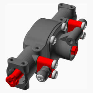
2 x Axle_Case_p1.stl
4 x Axle_part1_assembly
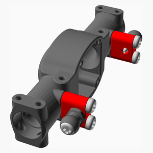
Install both Axle_part1_assembly on the Axle_Case_p1 with 4 M2 self tapping screw 12 mm.
Top
Qty
Description
2
Ball bearing MR63ZZ 5mm x 8mm x 2.5mm
8
Screw M2 pan self tap x 6mm
2 x Axle_Case_p2.stl
4 x Drive_Shaft.stl
2 x P14_G34.stl
2 x Axle_part2_assembly
2 x G34_assembly
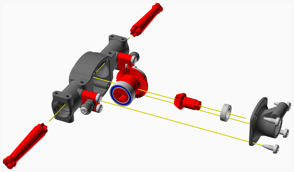
Insert G34_assembly in the axle.
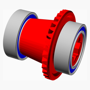
Install ball bearing MR63 on P14_G34.
Install P14_G34 in Axle_Case_p2.
Fix Axle_Case_p2 on Axle_Case_p1 with 4 M2 self tapping screw 6 mm.
Insert both Drive_Shaft in axle. Note: there is no ball bearing on the shaft.
Top
Qty
Description
8
Screw M2 pan self tap x 10mm
4 x 5_5_ball_Open.stl
2 x Axle_part1_1_L_assembly
2 x Axle_part1_1_R_assembly
2 x Axle_part3_assembly
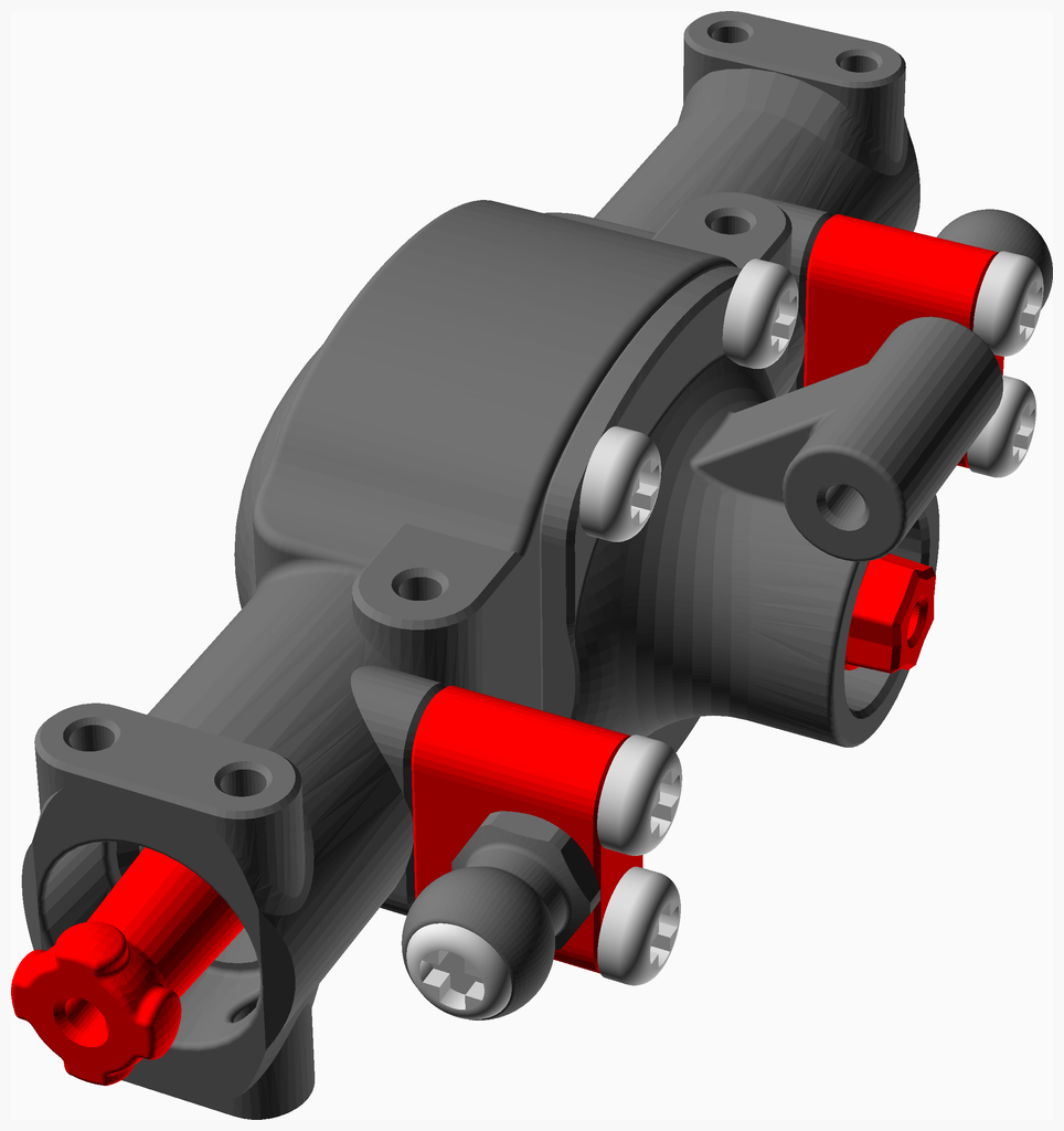
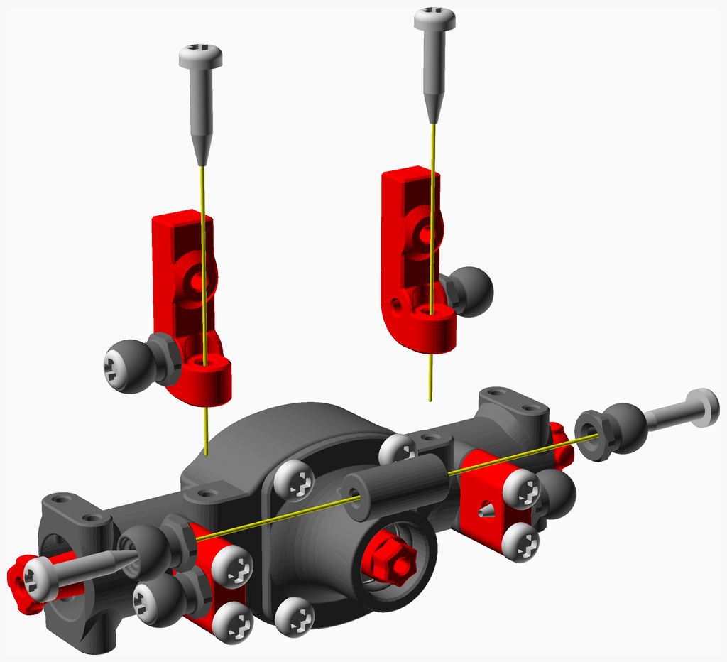
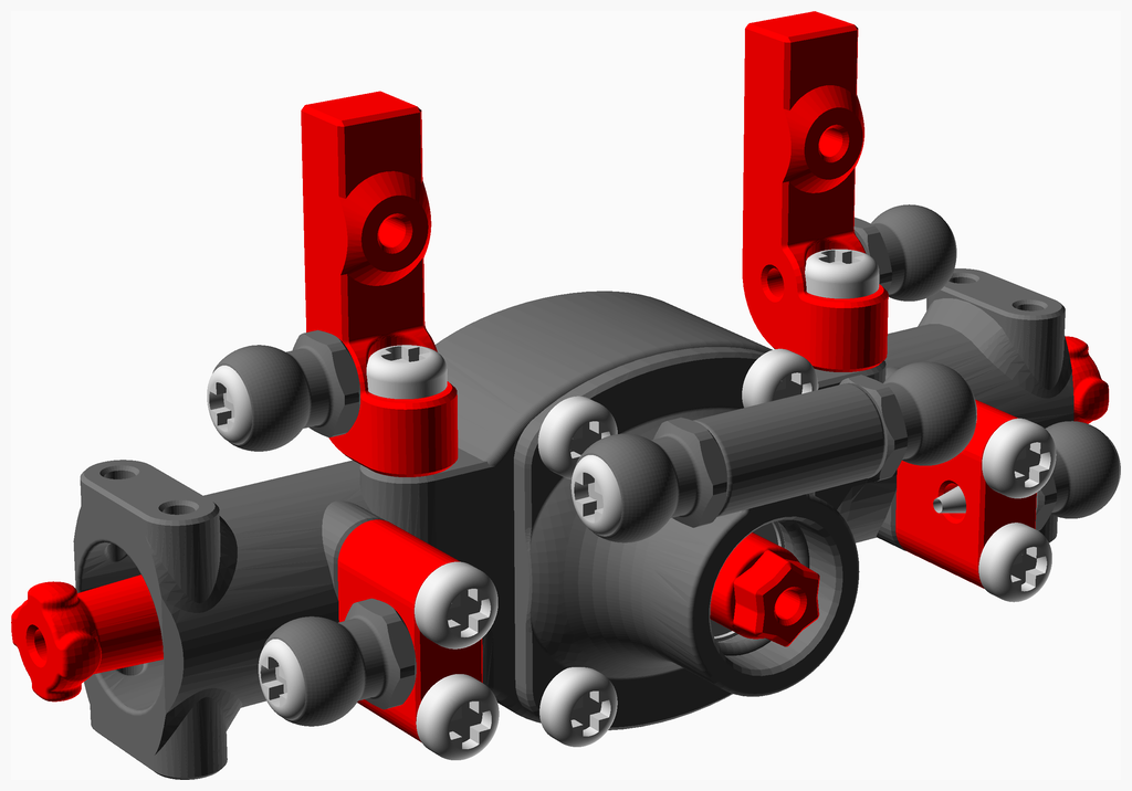
Install two 5_5_ball_Closed on Axle_Case_p2 with M2 self tapping screw 10 mm.
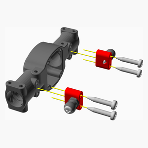
Install the servo holders (Axle_part1_1_L_assembly & Axle_part1_1_R_assembly) on Axle_Case_p2 with 2 M2 self tapping screw 10 mm.
Top
Qty
Description
16
Screw M2 pan self tap x 5mm
2
Screw M2 pan self tap x 6mm
8 x Axle_Case_p3.stl
2 x Center_Drive_Cup.stl
2 x Axle_part4_assembly
2 x Hub_L_assembly
2 x Hub_R_assembly
Install the Center_Drive_Cup in the Axle with a M2 self tapping screw 8 mm.
Install the Hub_L_assembly along with two Axle_Case_p3 with 4 M2 self tapping screw 5 mm
Install the Hub_R_assembly along with two Axle_Case_p3 with 4 M2 self tapping screw 5 mm
Top
Qty
Description
4
Screw M2 pan self tap x 6mm
2
RC servo SG90
2 x Axle_part5_assembly
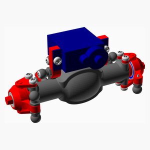
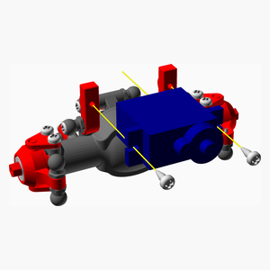
Install the servo SG90 with 2 M2 self tapping screw 6 mm.
Top
Qty
Description
2
Screw M2 pan self tap x 6mm
2 x Servo_Horn.stl
2 x Axle_part6_assembly
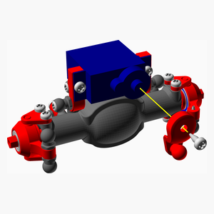
Install the servo horn using the screw that came with the servo.
Top
2 x Ball_Link_62mm.stl
2 x Axle_part7_assembly
2 x Servo_control_link_assembly
Install a Servo_control_link_assembly from the servo horn to left hub.
Install a Ball_Link_62mm between the two hubs.
Top
Qty
Description
1
Ball bearing MR63ZZ 5mm x 8mm x 2.5mm
4
Screw M2 pan self tap x 5mm
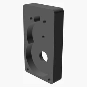
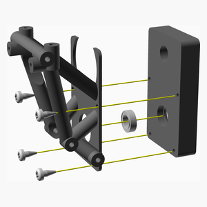
1 x frameFront_v2_1.stl
1 x gearboxFront_v2.stl
step 1
Top
Qty
Description
1
Smooth rod 2mm x 10mm
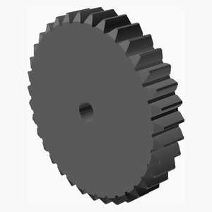
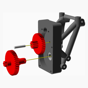
1 x firstStageGear.stl
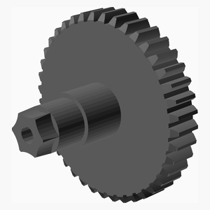
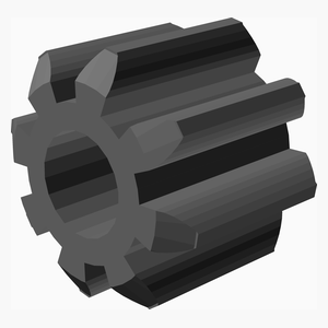
1 x secondStageGear.stl
1 x gearBox_part1_assembly
Make sure the whole in firstStageGear is 2 mm using a 2 mm drill.
Make sure the whole in frameFront_v2_1 is 2mm using a 2 mm drill. Do not go through the case.
Put some grease on both side ot firstStageGear.
Insert the 2 mm rod in the firstStageGear. Then insert in the frameFront_v2_1. Make sure it turns freely.
Put some grease on both side ot secondStageGear.
Insert secondStageGear on top of firstStageGear.
Top
Qty
Description
2
Screw M2 pan self tap x 6mm
1
motor 130, 6 volts
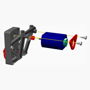
1 x Motor_Holder.stl
1 x gearMotor.stl
1 x gearBox_part2_assembly
If your motor didn't come with a 8 thooht then insert the gearMotor onto the motor
Insert the motor. Make sure the gear are turning fine.
Install the Motor_Holder with 2 M2 self tapping screw 6 or 8 mm.
Top
Qty
Description
1
Ball bearing MR63ZZ 5mm x 8mm x 2.5mm
1 x gearboxBack_v2.stl
1 x gearBox_part3_assembly
Top
Qty
Description
2
Screw M2 pan self tap x 6mm
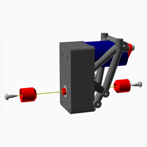
2 x Center_Drive_Cup.stl
1 x gearBox_part4_assembly
Insert both Center_Drive_Cup with 2 M2 self tapping screw 6 mm.
Top
Qty
Description
4
Screw M2 pan self tap x 12mm
1 x frameBack_v2_1.stl
1 x gearBox_part5_assembly
1.Install the frameBack_v2_1 with 4 M2 self tapping screw 12 mm.
Top
Qty
Description
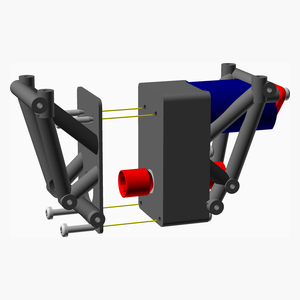
4
Screw M2 pan self tap x 6mm
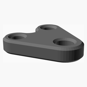
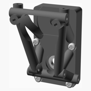
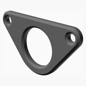
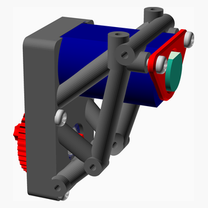
1 x plate_long_v2.stl
1 x gearBox_part6_assembly
1.Install the frameBack_v2_1 with 4 M2 self tapping screw 12 mm.
Top
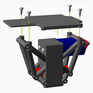
Qty
Description
12
Screw M2 pan self tap x 10mm
12 x 5_5_ball_Open.stl
1 x gearBox_part7_assembly
Top
Suspension Part1 Assembly
4 x Ball_Link_29mm.stl
4 x Ball_Link_41mm.stl
2 x Axle_final_assembly
2 x drive_shaft_assembly
1 x gearBox_final_assembly
Proceed with one end at a time.
Install the 2 Ball_Link_41mm
Install the drive_shaft_assembly
Install the 2 Ball_Link_29mm
Proceed with the other end.
Top
Suspension Part2 Assembly
4 x shock_43mm.stl
1 x suspension_part1_assembly
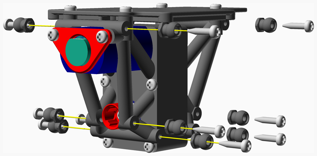
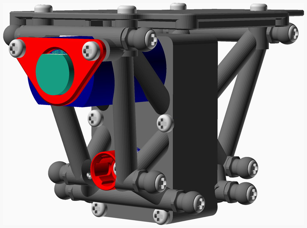
Install the shock. Pay attention to the opening at the ball joint: they should be facing up. This will make the shock bending downward when compressed.
Top
Qty
Description
4
Screw M2 pan self tap x 6mm
4
Screw M2 pan self tap x 8mm
1 x Center_Drive_Shaft_P2_15_5mm.stl
1 x body_v3.stl
1 x shock_46mm.stl
1 x wheel_26_5mm.stl
1 x suspension_part2_assembly
2 x wheel_left_assembly
2 x wheel_right_assembly
Install the 4 wheel with M2 self tapping screw 8 mm.
Install the body with 4 M2 self tapping screw 5 mm.
Top
