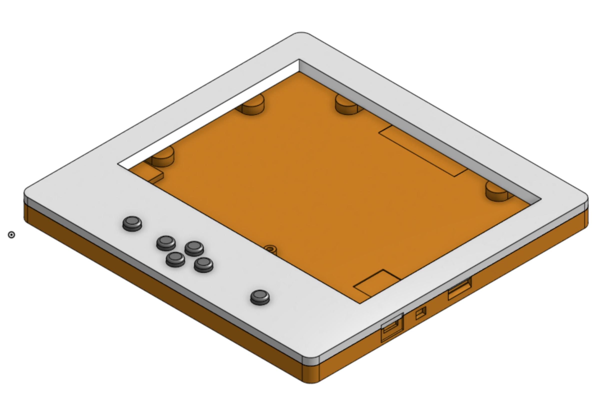
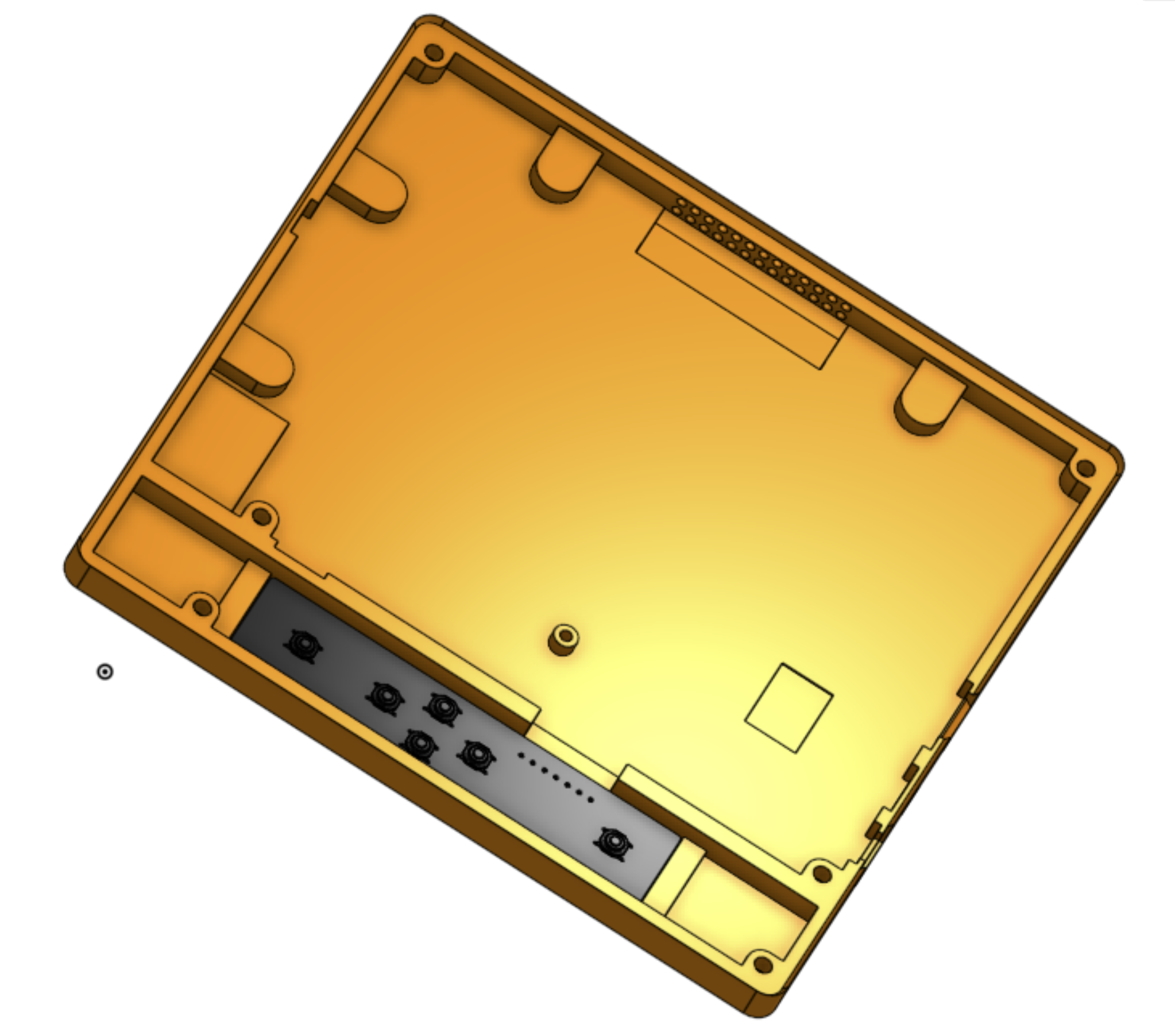
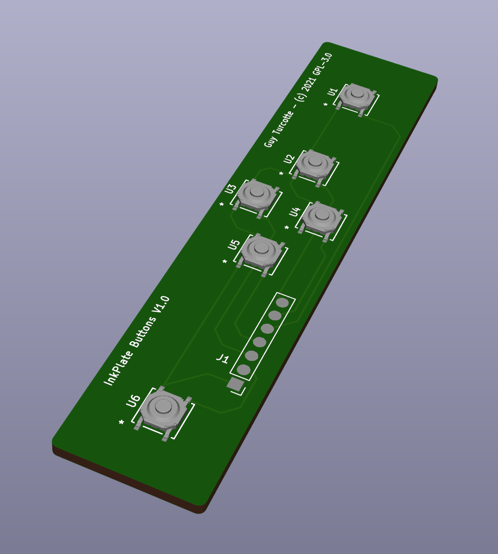
This is a change to the current InkPlate-6 case to add a small electronic board with push buttons below the mainboard. To do it, I took the original design from e-Radionica and extended a side of it, so the original portion of the case remains unchanged. The Mechanical CAD folder contains the complete STEP format design as well as the STL files ready for 3D printing. The Electronics folder contains the Gerber files for the preparation of the pc-board, as well as the schematic in PDF. I have used OnShape and KiCAD to complete this project.
- For the STL files, dimensions are in millimeters.
- Six buttons must be printed as well as the top and bottom casing. The buttons may have to be adjusted in size depending on the 3D printing results.
- The connection with the MCU23017 is done using wirewrap wires (or a flat cable) that are soldered at both ends using the following configuration (beware that the corresponding buttons numbers are inverted in the sequence):
   On the   |     On the     | Corresponding
Buttons PCB | InkPlate Board |    Button
------------+----------------+---------------
            |                |
   Pin 1    |      GND       |
   Pin 2    |      GPB7      |      U6
   Pin 3    |      GPB6      |      U3
   Pin 4    |      GPB5      |      U5
   Pin 5    |      GPB4      |      U1
   Pin 6    |      GPB3      |      U4
   Pin 7    |      GPB2      |      U2
- The squared pad is pin 1.
- On the buttons' pc-board, there is no through-hole, just pads on the surface to solder the wires. This is to ensure that the board will remains flat at the bottom of it's location in the casing.
- The three touch pads on the InkPate-6 pc-board must be disabled, the corresponding signals from the MCU23017 must be diverted to the GPBx pin holes on the main pc-board. This is done by desoldering the current jumpers and soldering them back on the other side. They are located under the following labeling on the board: "Touch pads".
- The GPIOB I/O bits of the MCU23017 corresponding to the GPB2 through GPB7 pins must have their internal pull-up resistor enabled.
- The buttons' pc-board must be of a standard height (1.6 mm). This to ensure proper spacing for the printed buttons. The board must be 'glued' at the bottom of the main casing using two-sided scotch tape. An alternative would be using a very small amount of hot glue on the 4 corners on the top of the buttons' pc-board. This is to permit easy removal in case of problems.
- The button switches' part number is C&K PTS526 SK15 SMTR2 LFS 5.2x5.2x1.5 mm. They are very common (For exemple, Mouser part # 611-PTS526SK15SMR2L, Digikey Part # CKN12221-1-ND, or other manufacturers equivalent). The 1.5 mm height is important to insure proper spacing for the printed buttons.
The original licensing from e-Radionica remains GPL-3 for their design as well as all supplied files in this project.


