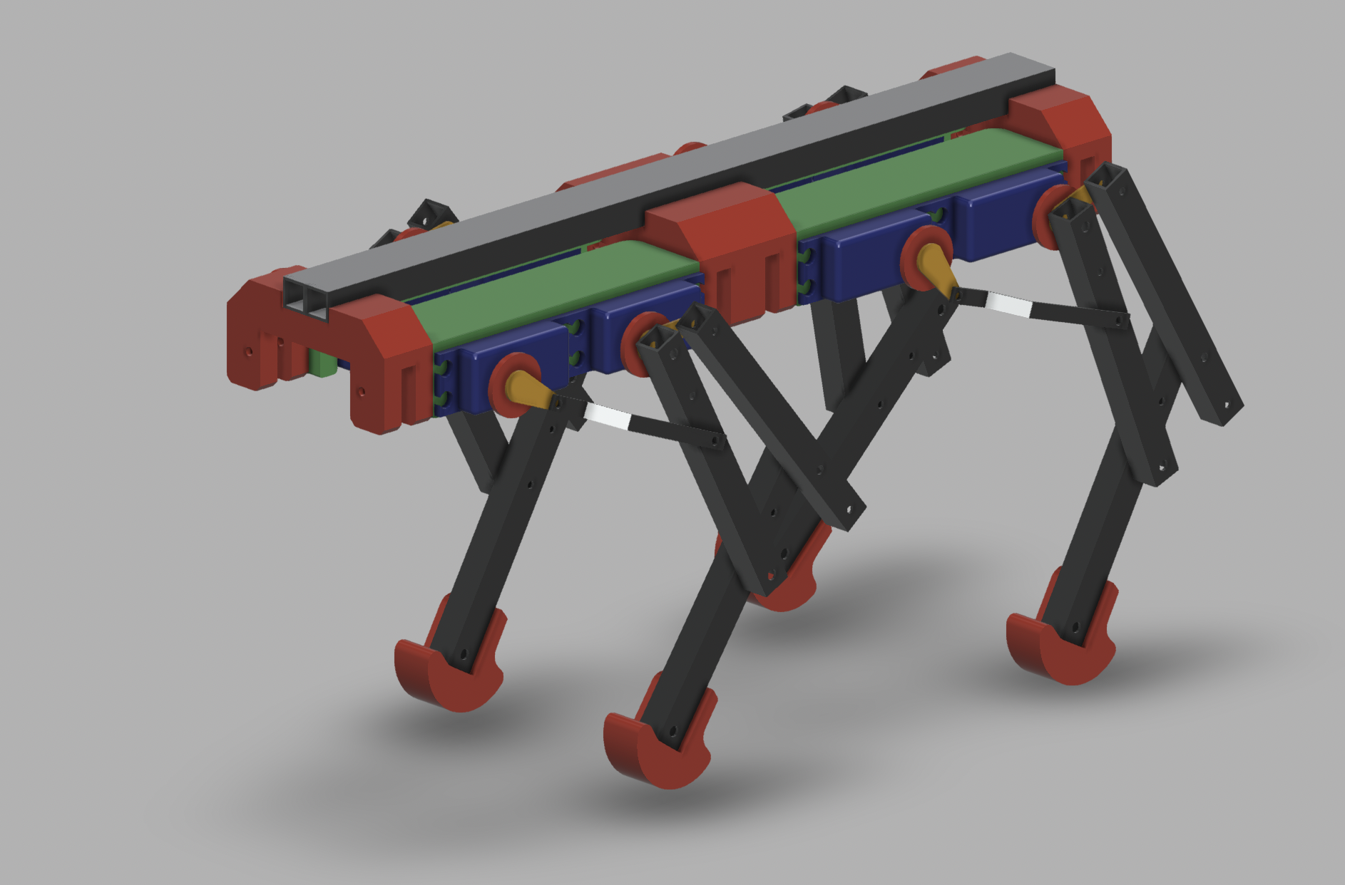
Currently a new version is in the development, hence all the code and data for the mk1 were moved ot the mk1 folder. 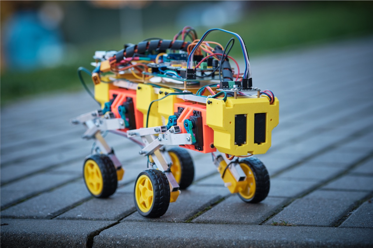
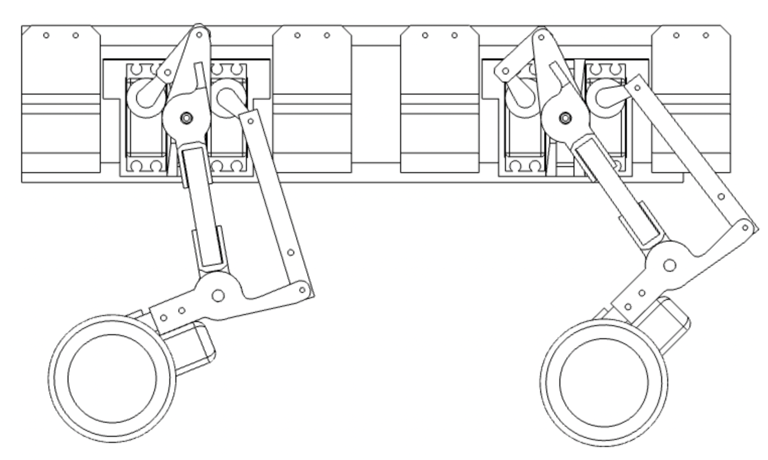
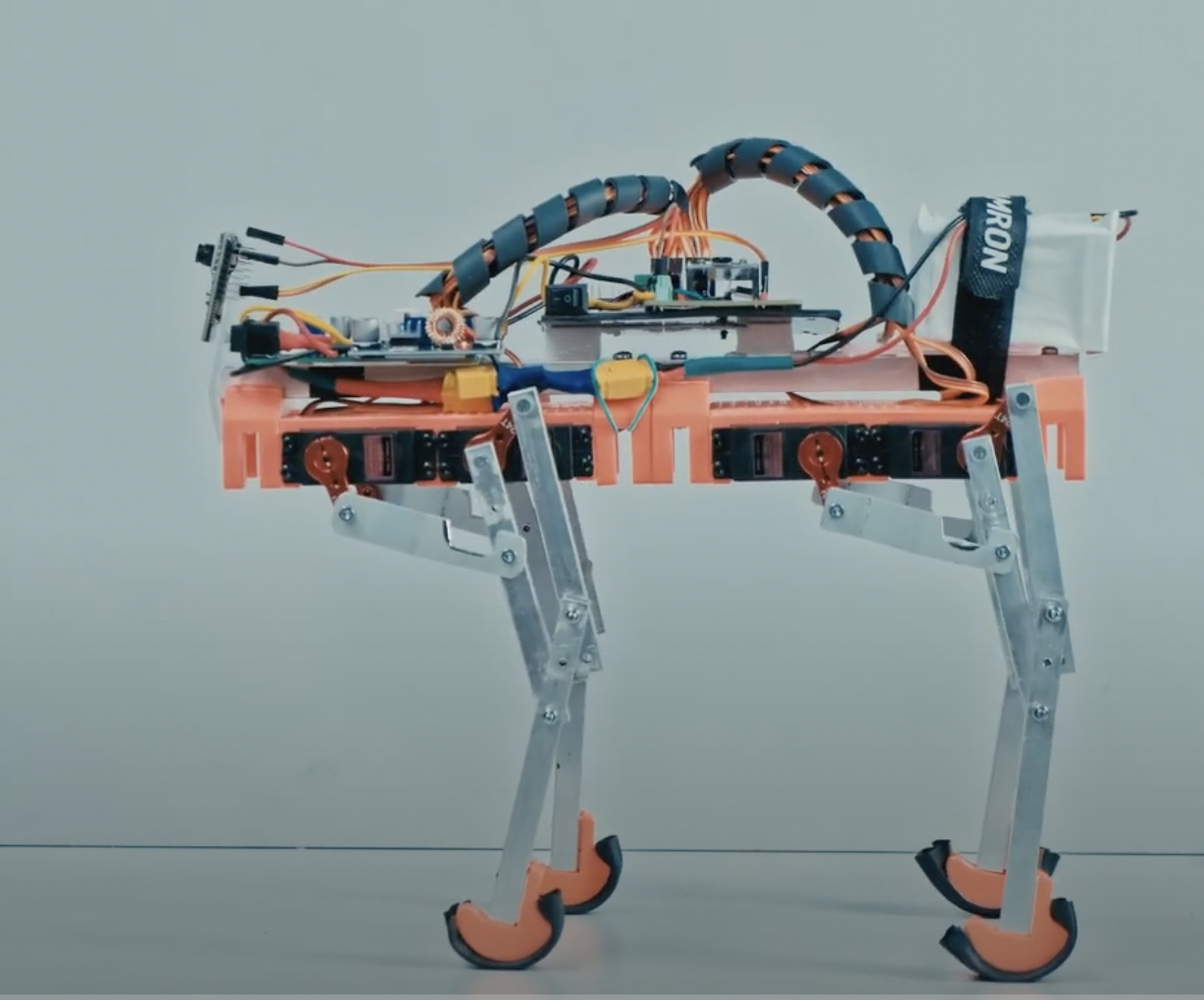
The main idea behind the mk2 is to add the 3th DOF for the leg. It is made by use of one additional servo for each leg. It is now heavily based on the 3d printed parts.
The - not so fully finished - 3d model made in Fusion 360 is available in the 3D_model folder. It covers all the required geometry in the form that was used for the build.
However some leg parts need to be printed as they are and as a mirrored ones - for the other side. As this project will move forward - the model will be updated to the full one.
Additionally all STL files (for both sides left and right) that were used for printing and build are in the 3D_model/STL folder.
To build the Aron the following components are needed:
-
The 3D printed parts
- 2x End Mount
- 2x Middle Support
- 4x Leg Bracket
- Knee LR x2
- Motor R x2
- Motor L x2
- Top LR x2
-
The ESP32 as a main control unit
-
2x PCA9685 to control the servos
-
DC/DC converter for powering servo
-
DC/DC converter for the electronic
-
2 channel H control for the DC motors
-
BLT 05 BlueTooth unit
The main piece of software that is controlling the Aron is the mk2_firmware located in the Arduino folder.
The Aron Mk2 in basic level can be controlled by the set of serial commands. Those can be sent to the ESP32 main UART via either the USB connection of the module or via the used BT module.
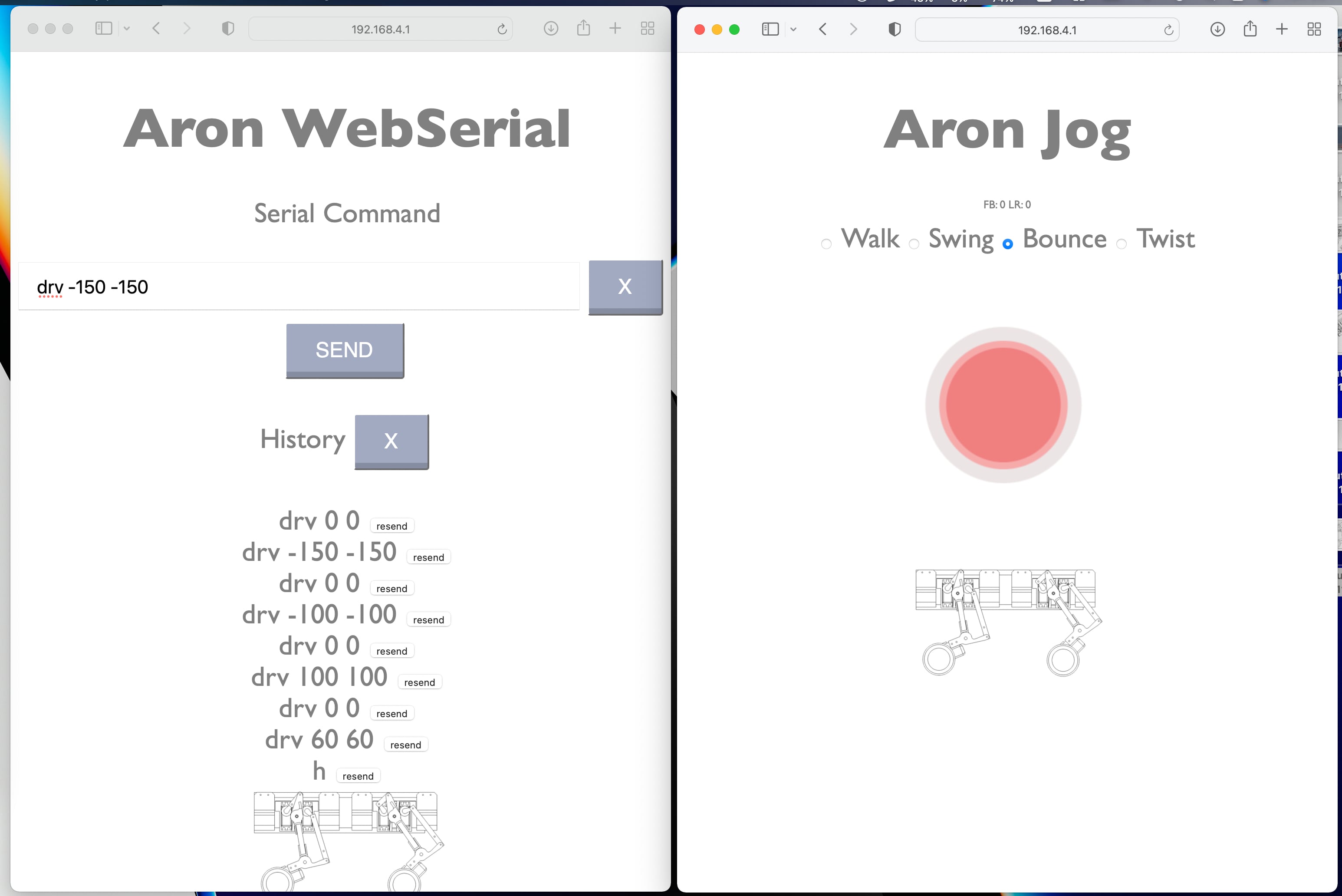
For the convenience and ease of use additional layer in form of Web Control Interface is added. It is made out of two main interfaces - the Jog and the WebSerial.
This interface is aimed for a real time remote control and allows to use the on screen joy to set live the behavior for:
- Walking around
- Swinging front and sideways
- Bounce up down
- Twist around.
This interface is available under:
http://ARON_PI/
This is a basic web to serial transciver. Works the same way as sending the serial commands directly via UART or BLE. Just is is available a sa webpage under:
http://ARON_IP/serial
At this stage the supported commands are:
-
test // run the simple test sequence - just moves all servos in loop.
-
power // toggle the power out
-
show // displaying back the current angles of all servos
-
h // resetting the servos to home position
-
reset // resetting the servos home to initial position - but no move make
-
ramp XXX // set up the ramp value input as 990 gives 0.99 ramp etc.
-
circ XX YY // moving front back (XX) left right(YY) by 2 arguments
-
move // triggering to make move to current incremental set
-
up FF BB // lowering or rising front (FF) and back (BB) legs by given value (-40 to 40)
-
leg L FF UP 0 // set data for single leg incremental model move - L leg number (1,2,3 or 4)
-
drv LLL RRR // move the wheels by 2 params in range -255 to 255 (0 is strop) for Left (LLL) and Right (RRR) wheels
-
s // full stop for wheels
-
twist TT // twist - to make twisted pose - param in range -50 to 50
-
walk // the sudo walk command
-
w // the sudo walk command
-
fake // to test the fake serial data
This is a work in progress project...
If you are interested please take a look at the vide playlist: YouTube Playlist
FLR as Four Leg Robot - is a hobby project aimed for experimenting with the idea of simple and affordable four leg robot build. It’s a playground for self study of the basic ideas of kinetic, stability and more.
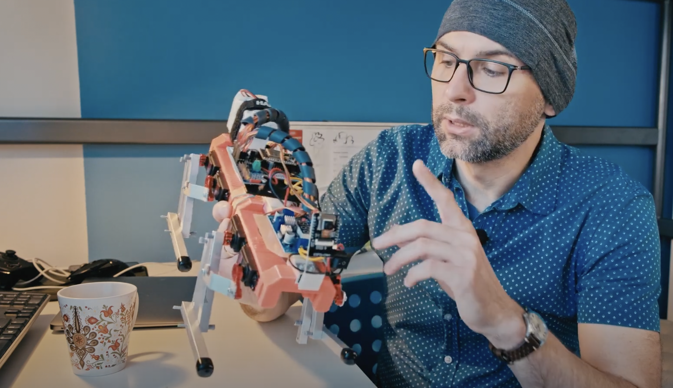
There is a set of videos - mostly in polish abut Aron and other robotic projects of mine.
Hardware is based on the generally available parts and some simple 3D prints. The 3D model made in Autodesk Fusion 360 is available to download in the „Mechanical_Model” folder of this directory.
fourleg/Mechanical_Model at main · tymancjo/fourleg · GitHub
And a 3d visualization under the link: https://gmail1957699.autodesk360.com/g/shares/SH35dfcQT936092f0e43c23261b81addf43c
Beside the mechanicals the main components are MG995 180 degree servos (or in general any servo of the similar size and torque) , the PCA9685 16-Channel 12-bit PWM/Servo Driver to drive them and and esp32 as a main controller of the system. But the main controller role can be covered as well by Arduino board of generally any kind.
Power source is made of the 2S2P set of 18650 Li-Ion cells with appropriate BMS system followed by 2 independent DC/DC converters that are stabilizing the voltage at 5V for servos (the V+ power on the PCA9685) and another 5V for the esp32.
In the prototype unit additionally an esp32cam is installed enabling some experiments possibility with simple computer vision. However it’s not a crucial element of the system.
The software is created in the Arduino IDE environment and utilize the supporting libraries from Adafruit and other ESP32 related ones. The main firmware file is the „esp32_servo_from_uart_WiFi” sketch located in the Arduino folder.
fourleg/Arduino at main · tymancjo/fourleg · GitHub
Separate software is available for the esp32cam module - and it is based on the available esp32cam example sketch delivered with the word manager resources.
Additionally some python helper programs are available - mostly used for plying around with preparing Aron poses and move sequences.
There are two main ways to control the Aron behavior. Firstly by the webpage.
When powered up the esp32 main unit setup a WiFi access point by a name BB.LAB.ARON and pass 123456789 (yeap! the super secure one). When connected to this network - an webpage is available under 192.168.1.1 IP address from where the pre-programmed behavior can be controlled by use of buttons. It’s extreakly simple interface and shall be quite self explanatory.
The other way of control is via the UART (serial port) communication to the main esp32. The transmission is set up tu go with the 115200 baud rate. But all of this can be modified in the firmware.
The way to send orders is to use the following string scheme:
<C,s1,s2,s3,s4,s5,s6,s7,s8>
Where: C - is the command id And the s1 to s8 are parameters.
The main commands are: 42 - makes the servos set up to the given angles where s1 to s8 are servo angles.
44 - recall one of the stored positions, where s1 is the number of position (counting from 0), s2 to s8 need to be set to some value (any).
46 - plays saved sequence, where s1 is the sequence number, and the s2 is number of repetition (1 to 20). S3 to s8 need to be set to any number.
55 - saves the servos as new stored position taking the given angles where s1 to s8 are servo angles.
