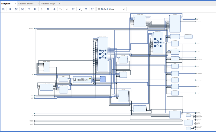
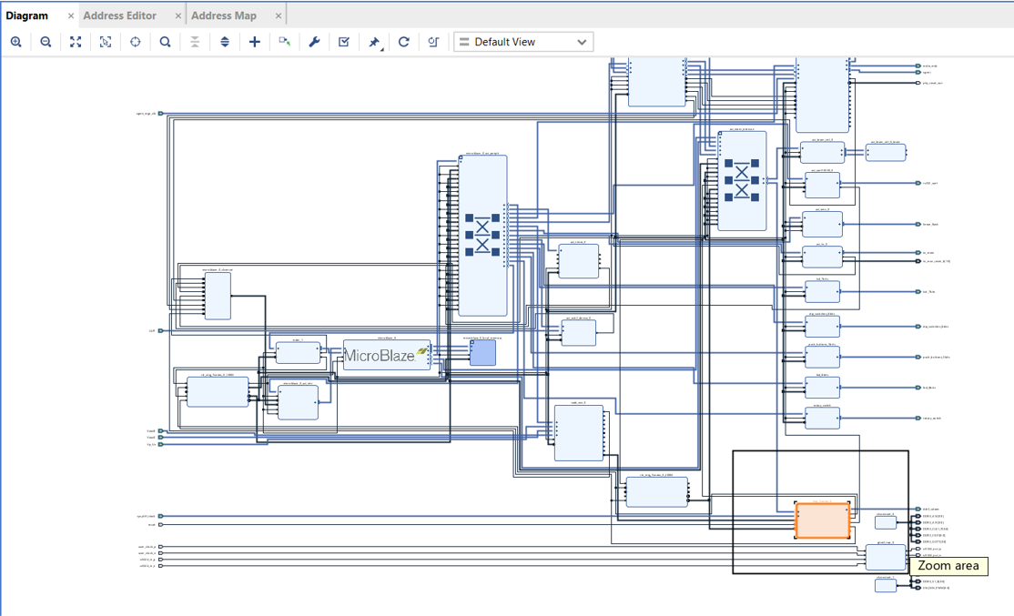
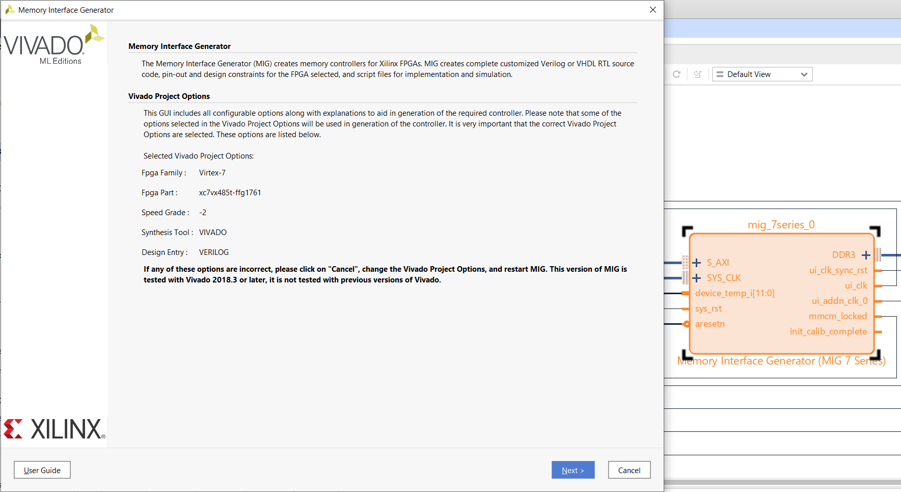
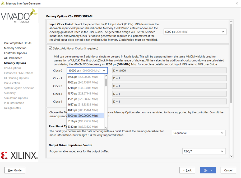
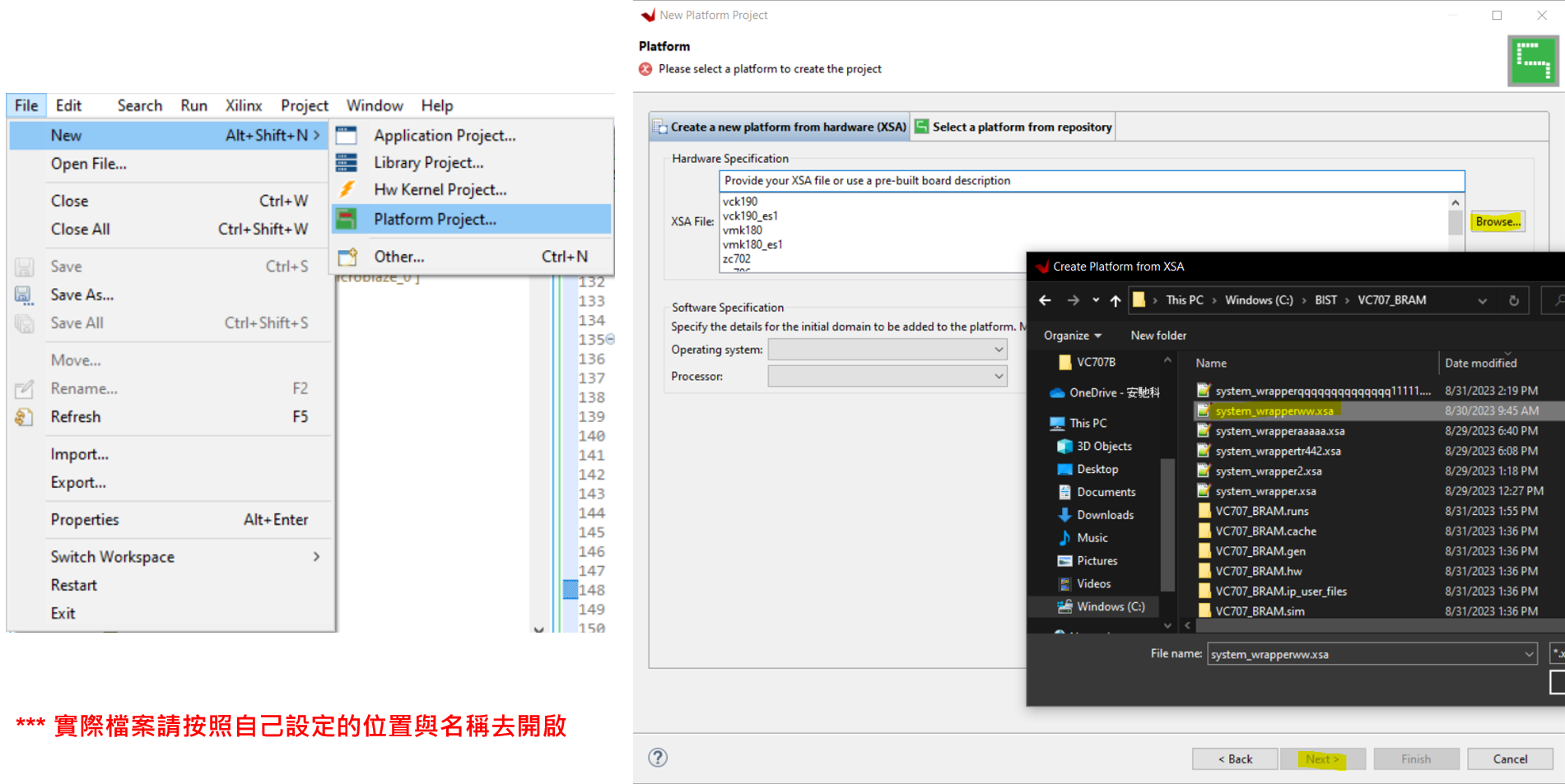
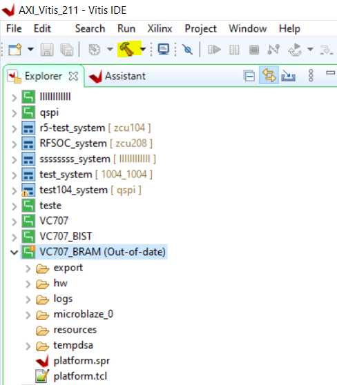
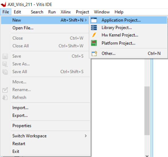
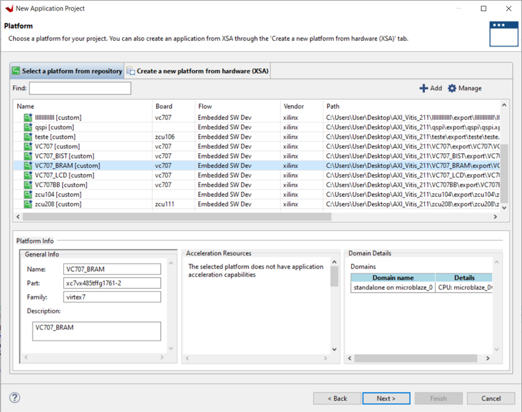
- This article mainly explains how to conduct official peripheral function tests on the VC707
Last update: 2024/05/18
-
Vivado Version: 2021.1
-
The process has been migrated from Vivado 2014.1 to 2021.1
-
The vc707_bist bd.tcl file in the directory has already been modified for Vivado version 2021.1. If other versions are needed, modifications must be made accordingly
- You can directly download the pre-packaged vc707_bist from the directory
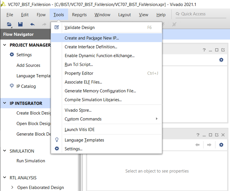
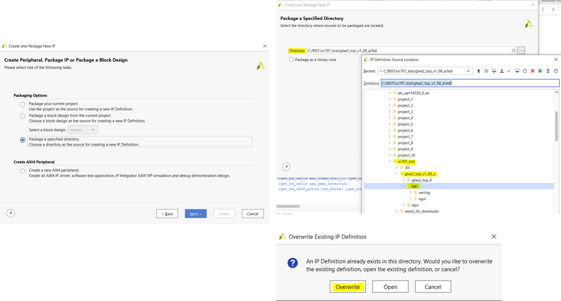
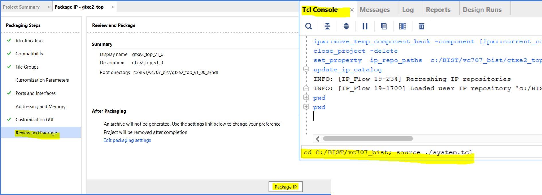
2. Select "Package a specified directory," and then choose the recently extracted vc707/gtxe2_top_v1_00_a/hdl directory
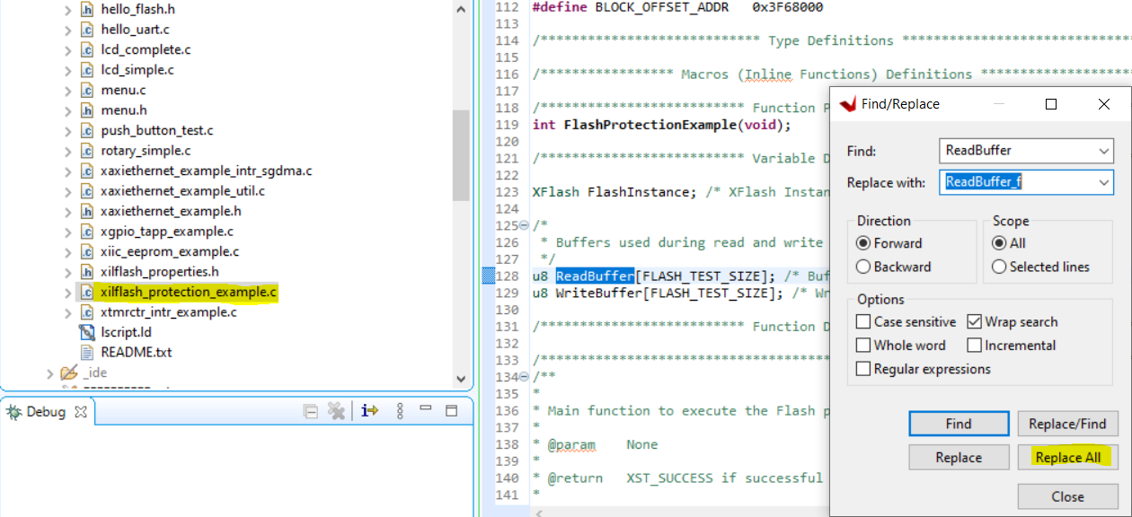
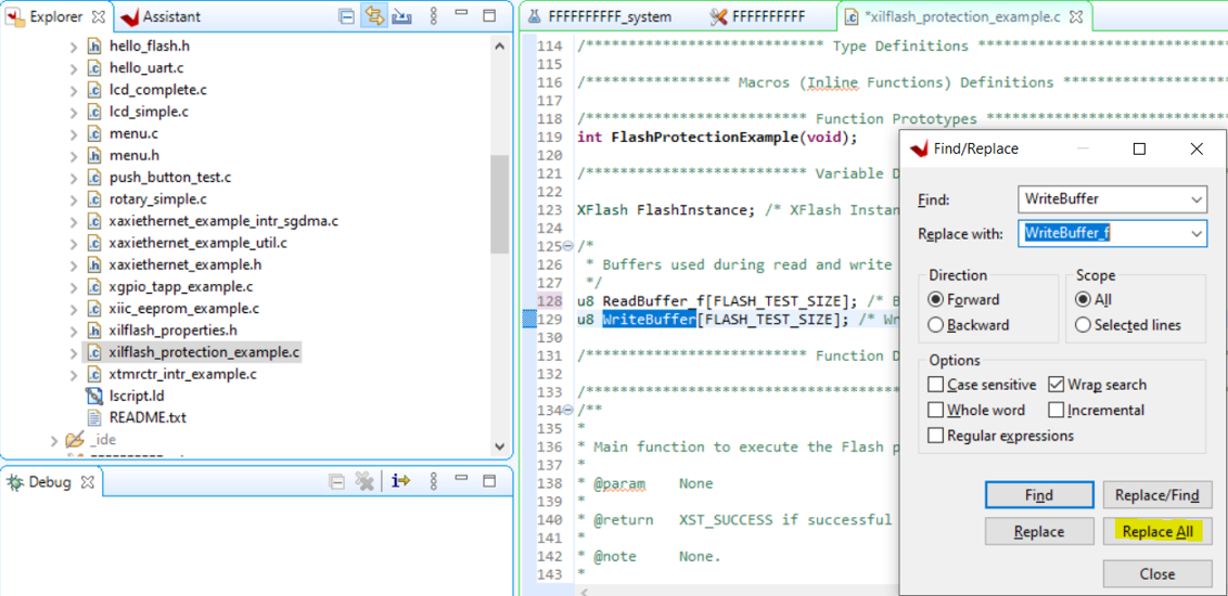
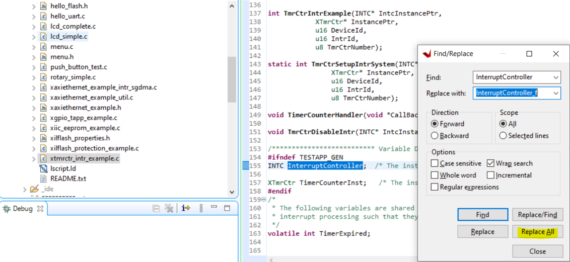
12. Modify the variable names ReadBuffer, WriteBuffer, and InterruptController in xilflash_protection_example.c
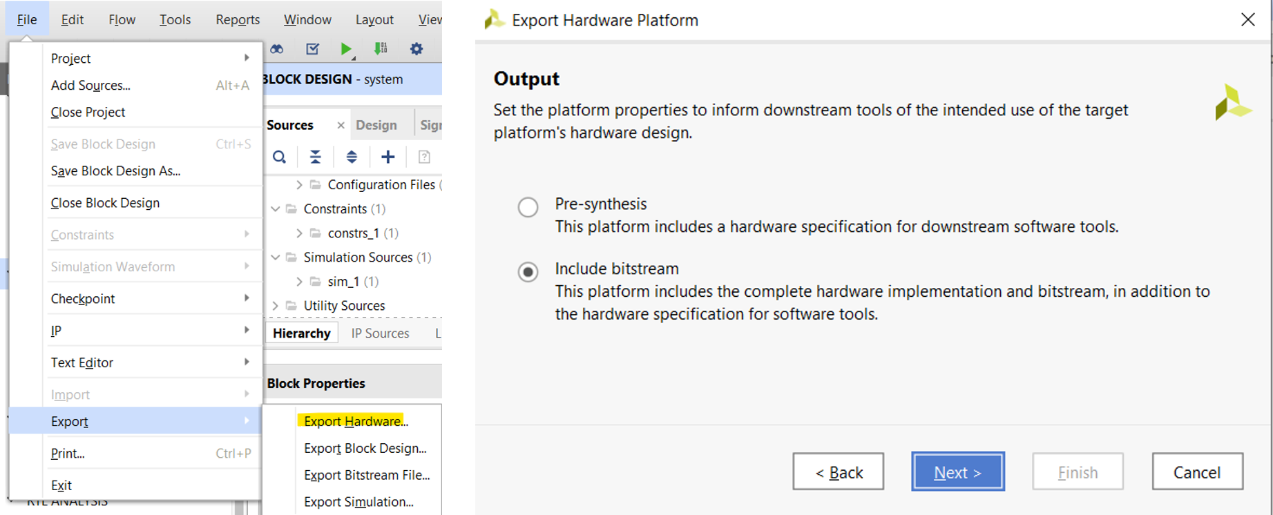
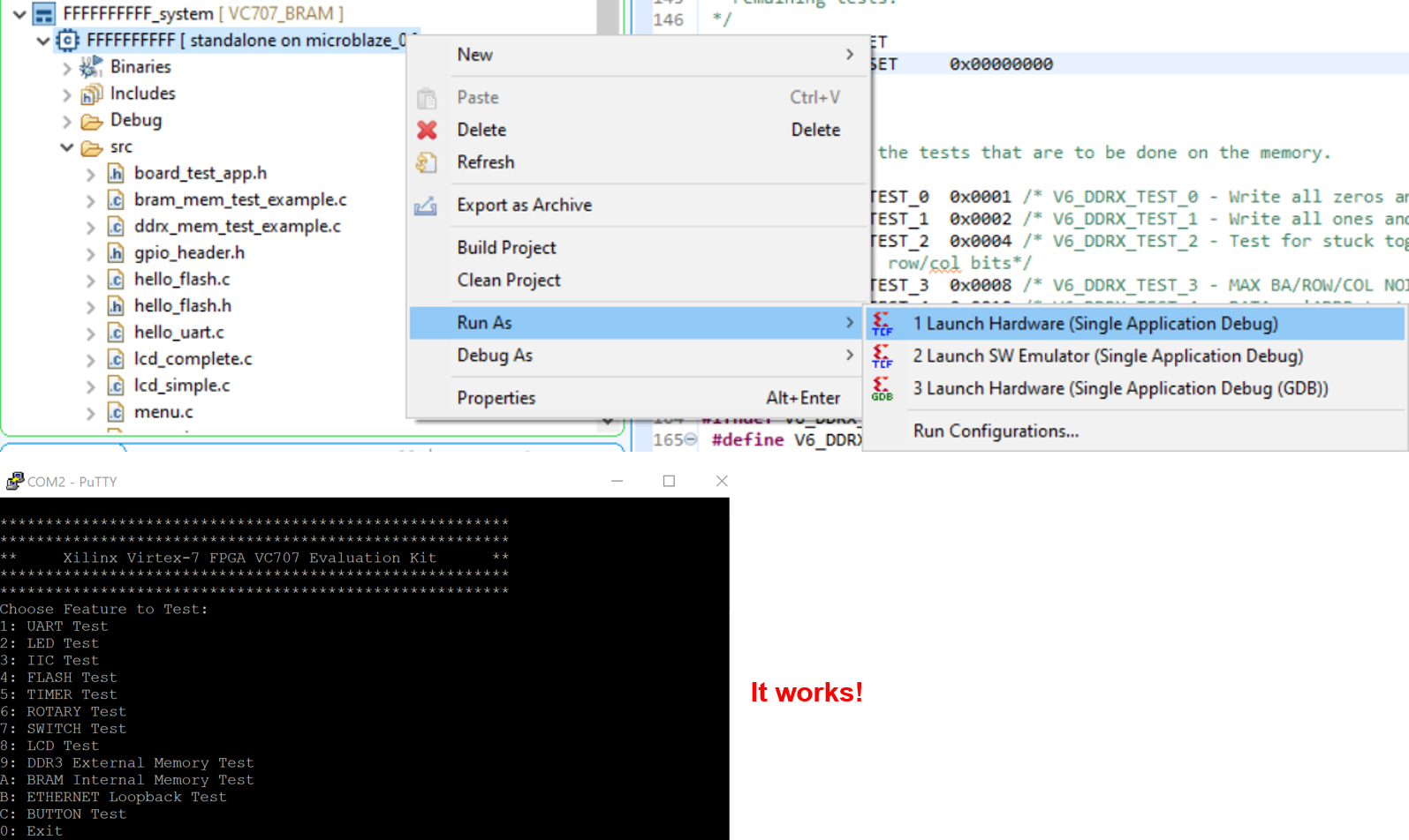
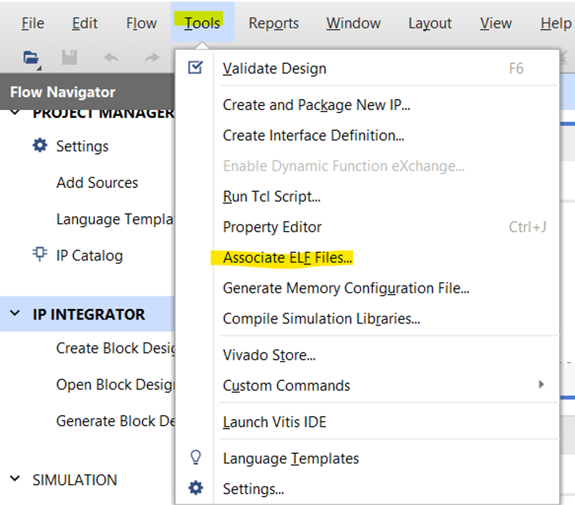
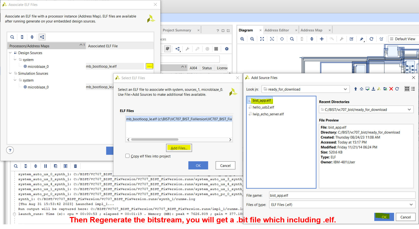
- You can link the Vitis-built Application .ELF file with the hardware design in Vivado, and then regenerate the bitstream with the functions written in Vitis for direct programming in the future
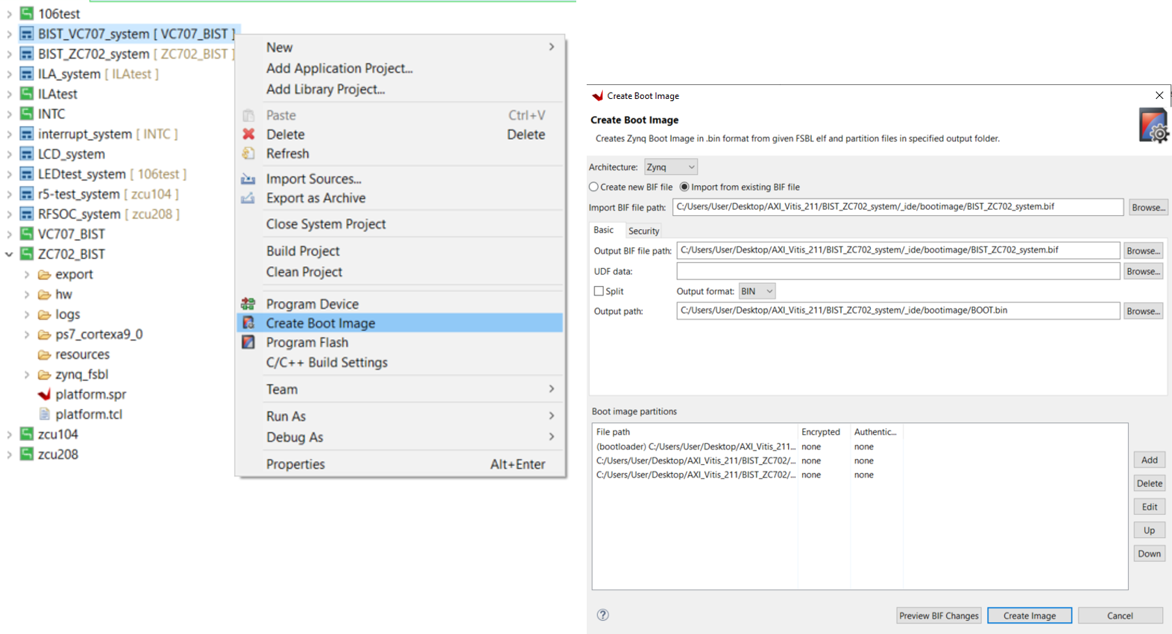
- For Zynq series, you can directly generate the Boot Image file (BOOT.bin) in Vitis
