Hello everyone. Every year the Engineering Physics Department at UBC creates a Summer robotics competition where 15-16 student teams are tasked with creating autonomous robots to preform a series of tasks and complete a mission. This tear's competition was themed after Marvel's Avengers.
Thanos has reached his evil goal of making half of the universe’s population disappear, brutally saving civilization from self-destruction by overpopulation. But in another parallel universe, his good twin brother Meta-Thanos known as Methanos has built an army of robots to counter his evil sibling’s intentions. Methanos is now sending these robots back in time to each one of the parallel universes to secure the Infinity Stones and rescue the Avengers. Meanwhile Thanos is deploying his own robot army to destroy the Avengers and gather the Infinity Stones in all universes.
These gods have engaged you, Engineering Physics students, to build them robots to go back in time to perform this purpose. As Thanos and Methanos look the same, you’re not really sure what side you’re on so you’d better make your robot able to function for both. As observers of just one of these universes, you will watch with delight or horror as your robots take part in the ultimate struggle between good and evil, between robots with flawless mechanical precision and those of questionable rigidity.
Two robots are positioned at the starting points and turned on. for hte purpose of the competition, one is called Thanos nad the other is called Methanos. However these two robots have the same objectives. Each robot has to follow a line up the ramp. From there , each robot has two different types of objectives :
- Retreat the Infinity Stones: Follow the black tapes to find intersections. From there, the robots must head to the post and pick up the infinity stone. The posts have the same circular base size with different heights. With this mission, the robot continues to follow the line back the its targetted gauntlet. There are six small and shallow holes on the gauntlet where the robot must drop the infinity stones. Robots could either drop the stones one at a time or they can pickup multiple stones and drop them at the same time at the end of the run. There are a total of 6 Infinity Stones and each one counts for 2 points if it is dropped in the gauntlet.
- Save the Avengers: There are a number pluchies randomly placed around the track. The mission with the plushies is to detect them and to guide them toward the plushy droping zone. There are two dropping points , one for Methanos and one for Thanos. But how does each robot know where to drop them ? Well each of these dropping zones has a Infra Red beacon used to create two different frequencies. Depending on the role , the robot must choose which IR beacon it must follow adn must drop the plshies there. Every plushy successfully dropped the has 1 point only and there are a total of 5 different plushies.
The important note to keep in mind is that every round of the competition is only 2 minutes long . In addition, all of these robots must have some method of handling collisions because for every restart, the team will have a -2 deduction from their overall score . Assisting the robot, like giving it a nudge or pushing the arm if it is stuck is allowd but will reduce any score from there on to 1/17 of the score. It is important to keep in mind that the strategy here is imperative for this competition.
Our initial strategy , after some time of working out possible solutions and testing them out (A list of these ideas like position tracking with a laser mouse, having a complicated 3-axis claw, using buke chains ) we decided to go with the strategy of picking up two stones from the shortest middle posts, going back to the gauntlet and dropping them off and then possibly going for plushies. As we though about going for plushies, we decided to use a camera and a Raspberry Pi to detect and go after the plushies. Since we decided to use a camera, we had the bold and dangerous idea of using the Pi Camera for the line following task as well. This decision led to a take a very different route for our robot design since the traditional method for line following is to use QRD sensors.
Our general strategy ended up being one that depends on the reliabiility and accuracy of hte robot in addition to relying on the speed. We needed speed since our robot was going into the opponent's territory. Since any collision is difficult to deal with in the middle of the competition, we decided to be wuick so that our robot would be able to return the stones to the gauntlet in less than a minute. From there on , we would decide to run again and restart or to go for the plushies. This way would have a guaranteed 4 points and this would give us an advantage in the competition. In addition to this, we decided to focus on some mechanical design in order to simplify the controll of the robot. for example a half circle in the front of the robot for parcking it accuratly in front of the posts. So, enought strategy talk ...
And so it began, our jurny towards the creation of Skin, Bark of Man. Why call it that ? Well because obviosuly Skin is the Bark of Man.
Well, first we needed to try out our idea of how the robot would look adn work. In addition, some of us working on software needed a prototype to tesk their code on.
Well, not much to work on. It was a very quick prototype created with a aluminum base ccreated with a waterjet cutter. We put slots in the middle so that we could position the components at different points on the chassis. We decided to use large and while wheel in order to increase the grip and the speed of movement. So for this prototype, we used a toy car wheel since in addition to having grip, it has a natural suspension effect for the control of the robot. Our robot had two caster wheel in the front as well. We put a webcam at the front of the robot and we used it for line following . the early versions of the code are in the github history. After about three days of testing we got it to work, kind of ...
After this we move to our other chassis version 2
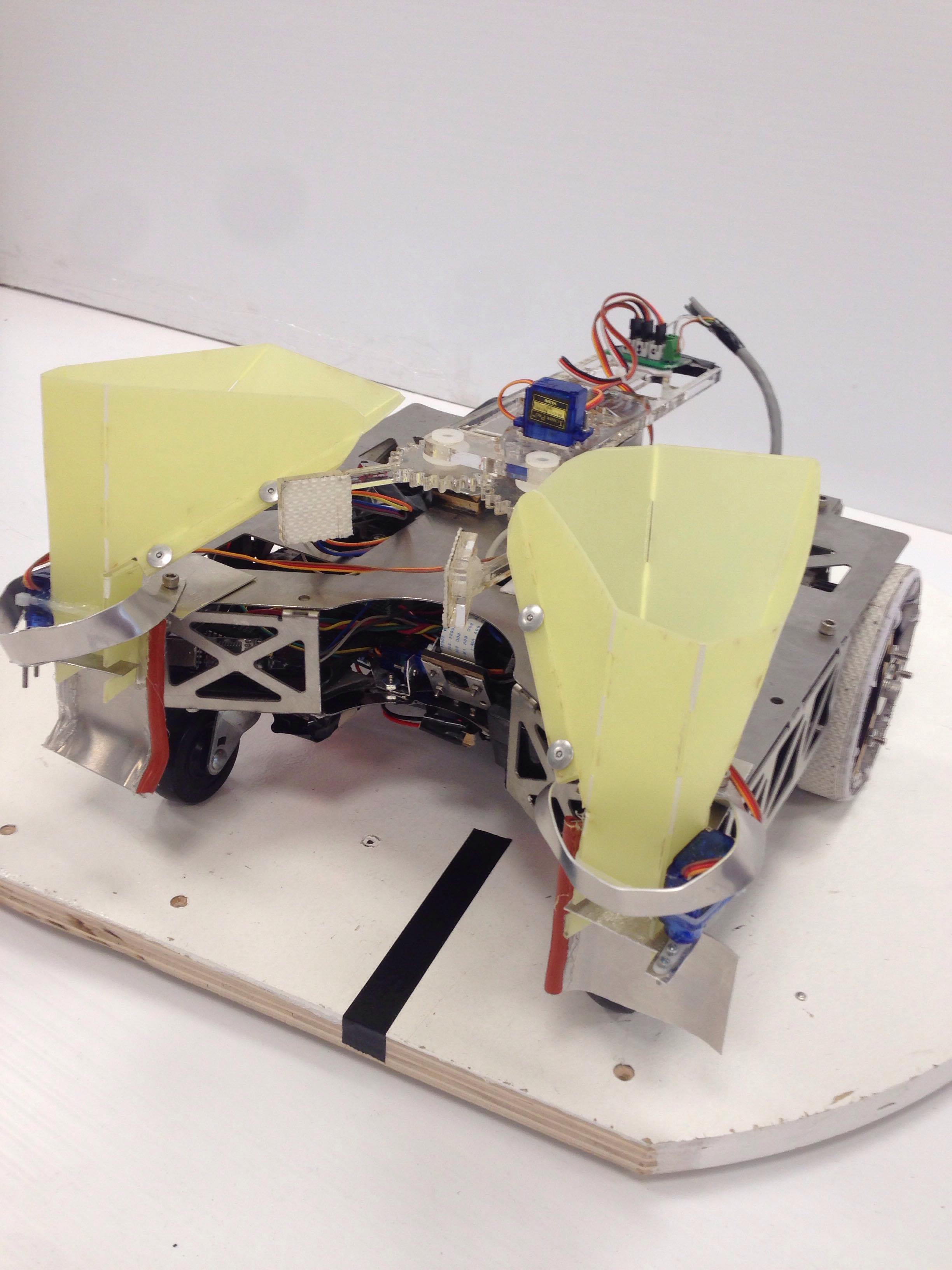
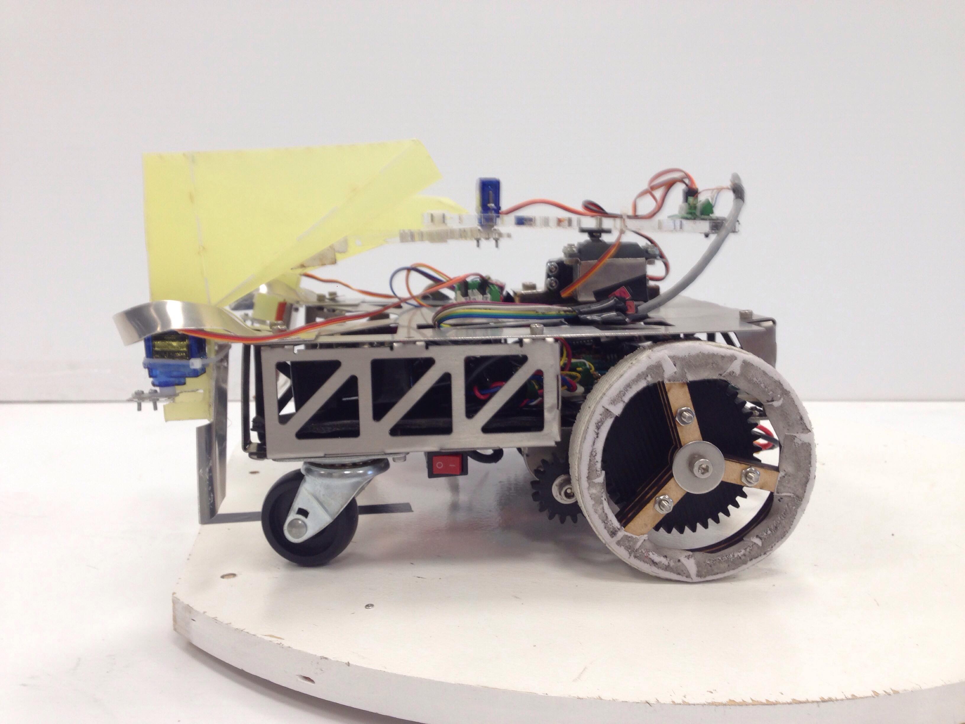
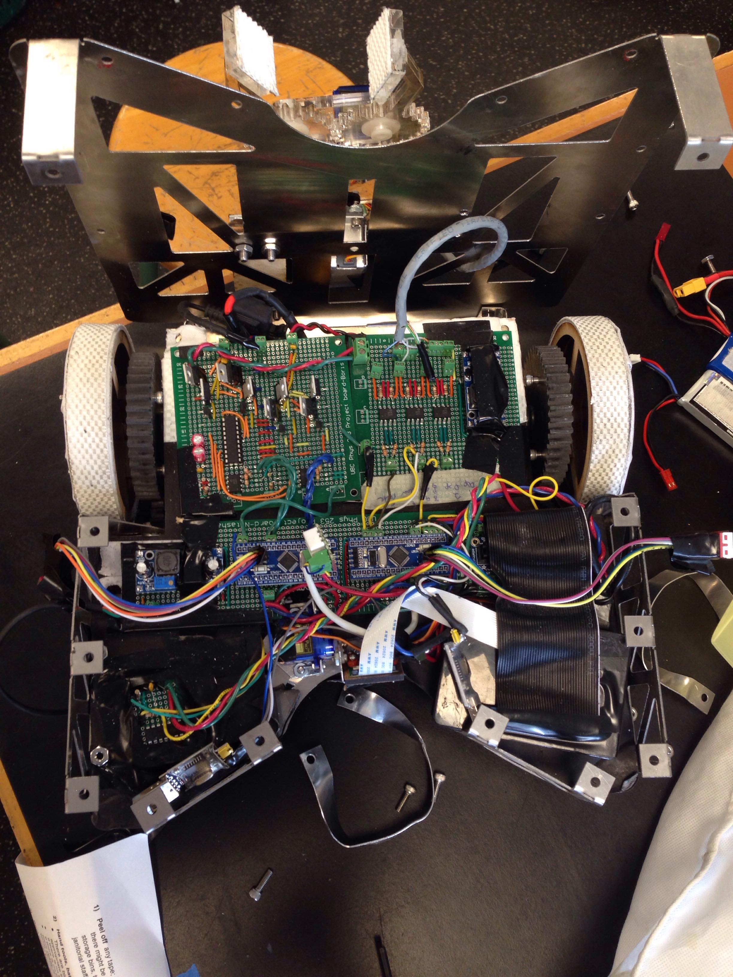
This chassis was designed to be sturdy. This chassis is one piece. That's right. One piece of aluminum was cut out using the waterjet cutter with holes and edge. Then this body was properly bent and different sides wereconnected to each other with fasteners, and nuts and bolts.While this is more difficult to build and connet , the benefit is the irgidity of the robot.Most teams chose to make their chassis out of hardboard with lase jet cutters. During the testing process and the competition, robot often fell out of the platform and collided with objects and other robots. The benefit of our metallic chassis was that the collisions and the dropping didn't damage our robot significantly and this proved to be very helpfull during the competition.
A couple of things to keep in mind for whoever decides to use a metallic chassis:
- Make sure that you electrical circuits do not touch the body. Shorting circuits is BAD. like VERY BAD .
- Try to make the chassis in a way that the circuits and interior of the robot could be change easily.
- Im not sure about this one -- If you are planning to use a robot that has two or three level and is tall, having the robot with too many nuts and bolts connection and too rigid would sometime reduce the control over the robot.
As for the wheels, we made the wheel out of (what I don't know ) with the same dimensions of the toy wheel. We also added layers of I forgot its name to add to the friction. The reason for changing the wheel was that ,believe it or not , we needed more friction !
We designed our chassis so that it would have a cutout in from of it with sloped walls leading to it. This way, we would need to be in the direction of the post and when we move forward, we will fit into the posts. We have a mechanical switch in the cavity that allows us to know when we have hit the post. This design choice ended up being a life saver.
In order to talk about the software, we first need to talk about our processors.
The pi is controlled using Raspian operating system which is a linux based OS for the Raspberry Pi. All of our programming in the Pi is done with Python.
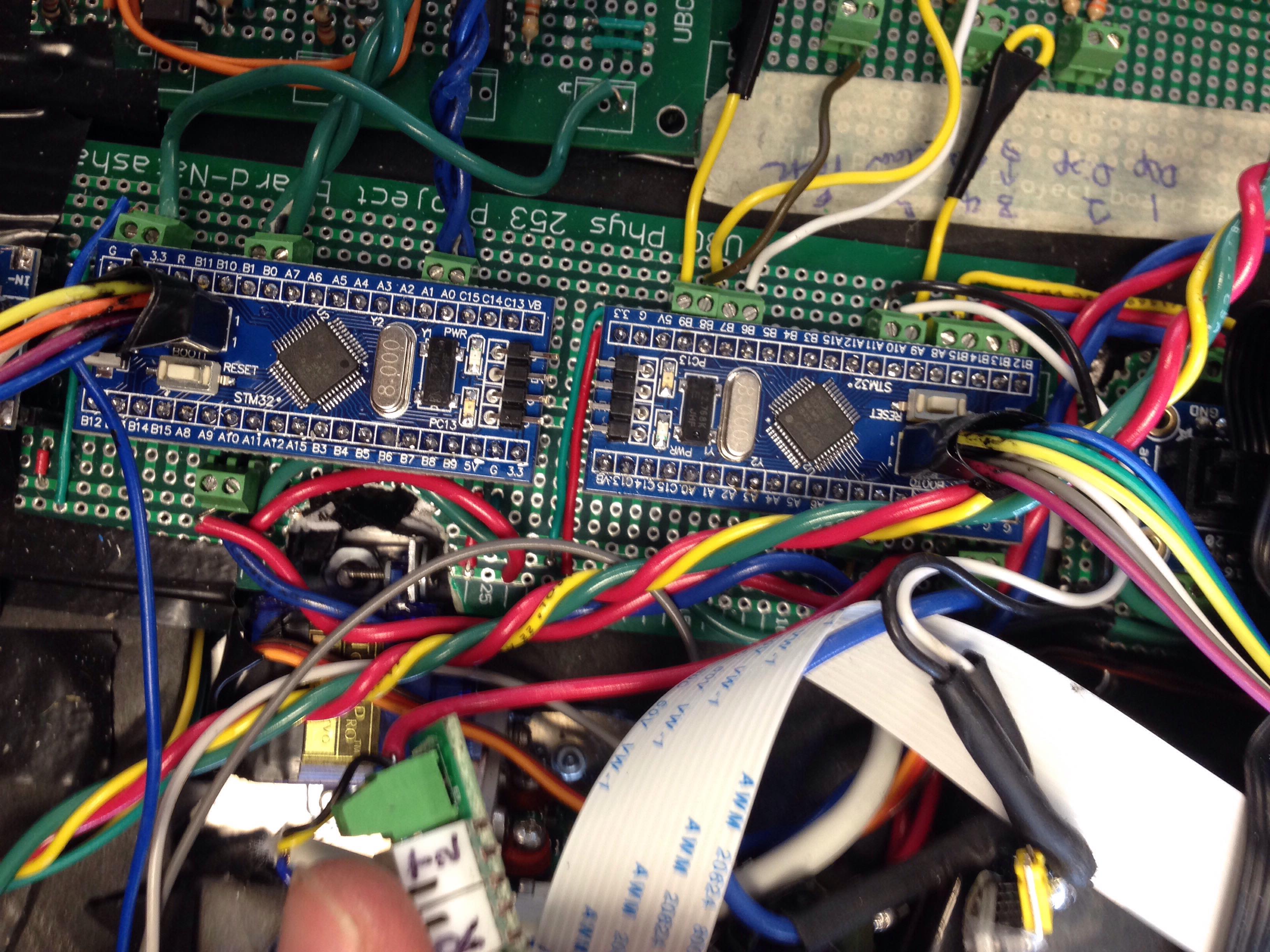
We were provided with free stm32 BluePills for the purpose of controlling the robot. These chips are small adn cheap and they can be programmed using C and C++.
We use a version 2, 8 MegaPixel Raspberry Pi Camera. The reason we used the version two model was because it had a higher framerate and with our algorithms, we were able to increse the framerate to 50 fps. Since we were planning on finding plushies and ther marks on the field, we needed to have the ability to change the angle of the camera. To this end, we attached the camera on a servo and controlled the servo with the Pi.
Every team was given a budget of 150 dollars and since we decided to use a camera , we needed to use a stronger controller board. Which is why we decided to use a Raspberry Pi in addition to the bluepill boards. Our controller hierarchy look something like this :
This way, the Raspberry Pi acts as the main controller. However, the raspberry pi did not have enough pwm pins and we preferred to control our servos and motors with the BluePills. The Pi processes the information from the camera frames and then sends commands to the motor controller BluePill through UART communication. The communication between these two boards is imperative since the raspberry pi constantly check which pwm signals is needed to follow the black tape. The other BluePill is only used to move the robot arm for picking up the Infinity Stones. Therefore the communication between the Pi and the arm BluePill is through two pins. The high and low states of those two pins are used to indicate the state of the arm (open, close, dron in dispensing). In addition to the arm, this second BluePill controlls the dispensing servos as well.
The code for both of out BluePills were mostly simple. The codes and comments are included in our repository. However the main focus of our code was on the our vision code implementation of the. Usually with QRDs , people tend ot use PID control. For our system, we use a similar concept. Our image processing works somethin like this:
- Take Grayscale frame from camera.
- Use a Gaussian Kernel to add to the continuity of the pixel intensity values and reduce black spots.
- Use a custom kernel to intensify line features and further reduce the black spectacles.
- Have a binary filter for turning the pixel values to black and white.
- Take out 5 or 6 horizontal lines out of the frame.
- Find the points on those lines where the derivative of hte color intensity changes a lot. In other words, we find the edges of the black tape.
- based on the position of the line edges, we find the position of the robot with respect to the center of the blakc line.
- From there on we have a PID controller just like any other line following robot.
We used a couple of libraries from OpenCV
A couple of notes for our PID control:
- We knew that for a normal line follower, we only technically need the Proportional and the Derivative, meaning a PD controller would do. However, since we were moving at a high velocity and the track had some rough turns, we discovered that we would need something like the Integral of the errors. For that purpose, we added statements to exponentially increase the error if the center of the black tape is too far out of the range, the error increases drastically to account for the sharp turns.
- One of the problems with the black tape is that it reflects the light. Meaning it is highly likely for the camera to see white circle around and on the black tape. This effects the line following controller specially at high speeds. In order to combat this, you need to reduce the speed of the robot and to play around with the binary cutoff value for blakc and white. It is important to keep this in mind and make sure no irregularities are seen with the binary cutoff value on the path.
- It is important to keep in mind the maximum, minimum and base speeds have a significant effect on the PID controller. To top that off, so does the battery voltages. You would use battery regulators to keep the voltage provided constant but then you may risk capping out the current provided. So we needed to make sure we are having our batteries at a know range of voltages.
- Keep in mind the speed of the algorithm. Given that most PID controllers with line followers use a dedicated microcontrollers and run in a range of 1000 updates per second.
One other important piece in the code is the detection of intersection. To this end, we always checked the length of the black line. If the length of the black line is larger than normal, we count that as a detected intersection. Again, the speed of the robot and update time for the algorithm really effect the detection of intersections.
We did have time to test out a couple of other ideas. For example, We used colorfiltering to find the plshies. However, since time was short we never actually ended up creating a full system for dropping off the plushies on the droping zone. There were marking on the posts and the gauntlet however they were damaged during the practive runs and we decided to use fixed turn and rotations for going into the posts.
Time to talk about the arm
The arm itself was coposed of three servo motors. One for changing the Z-axis angle, anotehr for the XY-plane angle and the other for closing and openning the arm. One of the main reasons we decided to use this arm was its reliablitiy.
Given that we arrive at the posts, we were almost always able to pick up the stones. One main reason was the use of arduinos and the fact that the arm itself was rigid. The gens were all in different hshapes and sizes so the arm grip and its position were important, making servos a viable option. The arm itself was made out of I FORGOT to make it as lightweight as possible.
After the arm picks up the stones, it drops them into two yellow funnels. These funnels have servos at the bottom which open when we arrive at the gauntlet in order to drop the stones into the shallow holens on the gauntlet. The entire arm and dispensing servoes are controlled by one BluePill which communicates with the Raspberry Pi.
And now, lets move on to the electrical components of the robot.
Here are a list of the electrical components:
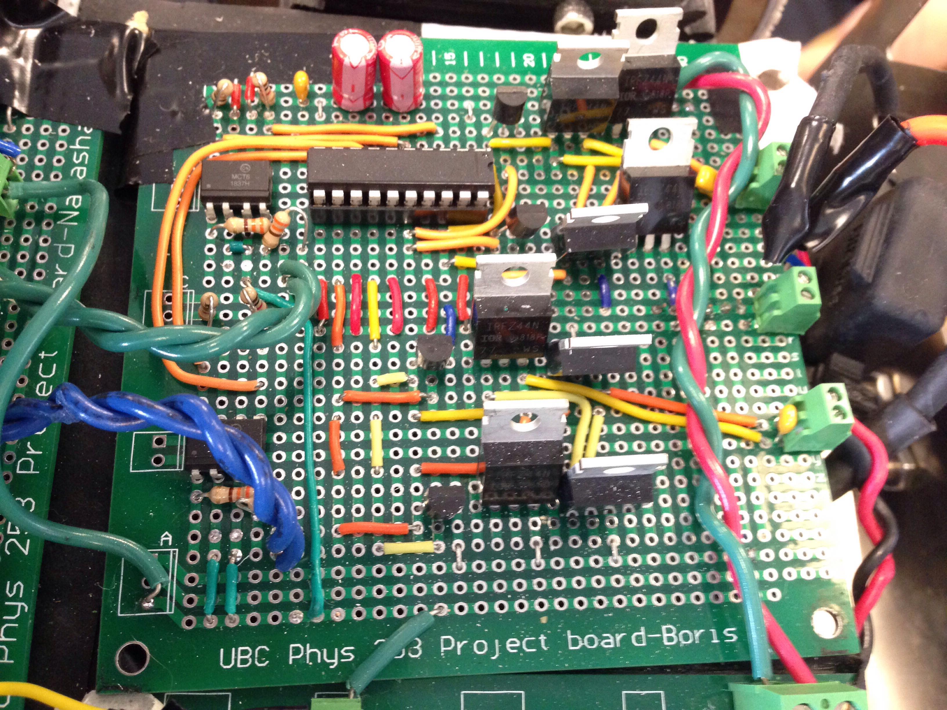
- H_bridge Circuit:
This circuit is our main drive controller board. The circuit simply takes ina PWM signal from the BluPill and send it to the motors. One component of the circuit includes an OptoIsolator which disconnects the ground of the mtotr from the geound of the circuit. This is because the motor creates a lot of noise on its channel and a could damage the BluePill. Therefore, it is imperative to seperate the two from each other. More Explanation requierd here. This circuit is powered with a 16 Volt lipo battery.
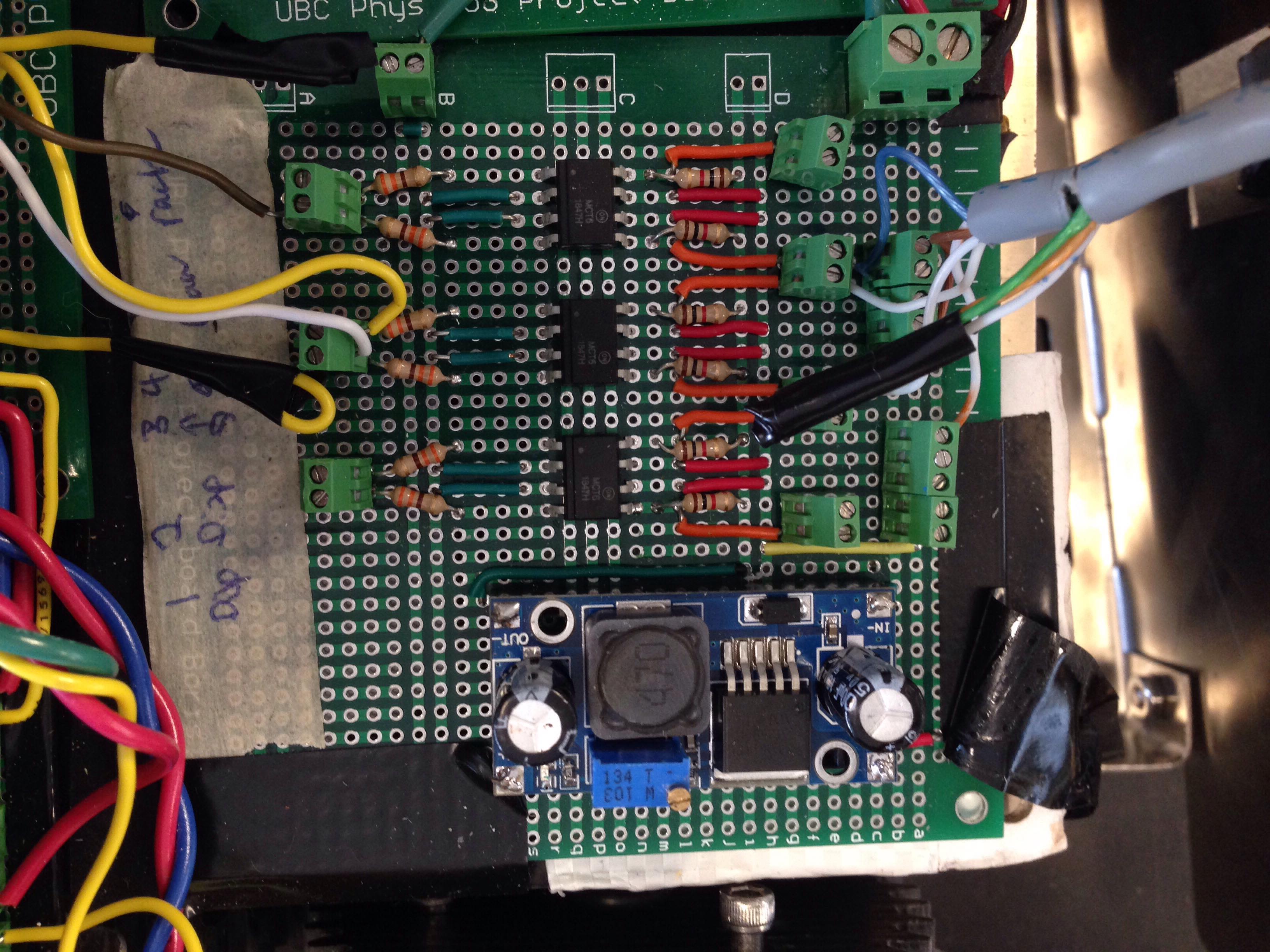
- OptoIsolator Circuit: The concept of this circuit is simple. We use this circuit to both power the servos and sends the pwm signals. One major reason behind using this circuit is because we decided to use the same 16 Volt lipo battery with a regulated voltage. Since that battery grounds with the Barber Colman motor, we needed to make sure the ground of the motor doesn't connect with the BluePills. Therefore we have 6 optoisolators. 3 for the arm and two for the dispensing tubes.
- BluePill circuits: This is a simple circuit which powers the two BluePills and has a regulator to bring down the voltage for 5 volts. This circuit is powered by a 8v lipo.
- Additional Components : The only other components are a debounced wsitch which is used to detect when we are at the post and the Raspberry Pi. The Pi and is conneted to the camera servo, switch and the two BluPills. The Pi itself is powered by another 8 volt lipo. There is a power switch connected to the 8 volt lipo for the Pi which regulates the voltage to 5 volts.
We cam in Forth
