I needed to switch lights in a barn located 100 yards from the main house using Loxone.
Additionally I want to be able to have traditional switches for local control.
The range is too far for Loxone Air, otherwise a Nano Air would have been ideal. I did install an Ethernet cable to the barn for future expansion, a security camera, or other needs.
I found the following switch:
http://www.rutenbeck.de/produkte/c/ip-aktoriksensorik/p/tcr-ip-4.html
Available from Conrad:
http://www.conrad-electronic.co.uk/ce/en/product/976282/Rutenbeck?ref=searchDetail
This has 4 relays that can be controlled using a web-page, or UDP.
Additionally the status of each relay can be retrieved using the http protocol.
The device has four local low-voltage inputs that can be used to switch the relays with local switches.
It fits on a din rail, needs 230V for operation, and has an input for an optional temperature sensor.
Initially you need to connect a PC with a static IP address of 192.168.0.1 to the Rutenbeck using a cross over cable. Only then can you access the web interface to set a different static address or a DHCP assigned address to the Rutenbeck.
I have noticed that it is hard to give the TCRIP4 a permanent, new, static IP address. If you can stick with the default address, 192.168.0.3, this is preferable. Obviously this does not work if you have more than one of these devices in your network.
Furthermore, other settings, such as wether to sync time using ntp, or to enable UDP operation (see below) were equally non-sticky.
In the configuration you can enable UDP operation and the UDP port 30303. Then it is a simple matter of sending a command using standard Loxone virtual output: OUT1 1 to switch on relay 1, OUT3 0 to switch off relay 3.
The UDP-command must be sent to Port 30303 and end with Hex 0H.
The problem I ran into however, is that like all other settings, the Rutenbeck device loses those settings, and therefore UDP access, at random times, although frequently related to power cycling. I therefore looked for a way of controlling the lights without having to change the Rutenbeck configuration.
By carefully looking at the code of the Rutenbeck, I found that it is possible to control the relays directly.
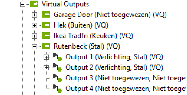
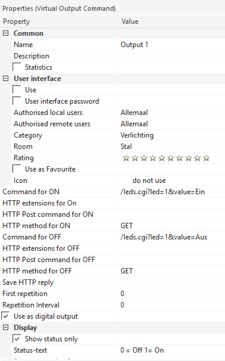
A request to http://192.168.0.3/leds.cgi=X&value=Ein allows led X (where X = 1..4) relay 1 to be switched on.
Changing Ein to Aus switches it off.
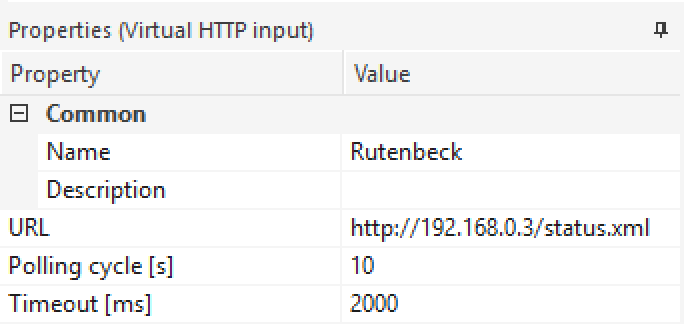
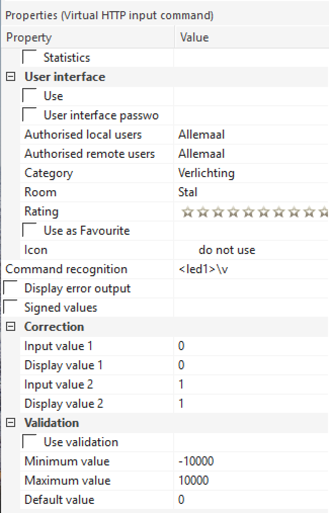
I also found a hidden HTTP request that returns the status of the relays (so that you can check if a local switch has enabled a relay). Go to http://192.168.0.3/status.xml and it returns:
<response>
   <led1>0</led1>
   <led2>1</led2>
   <led3>0</led3>
   <led4>0</led4>
   <pot0>nicht angeschlossen</pot0>
</response>
(Nicht angeschlossen means Not connected)
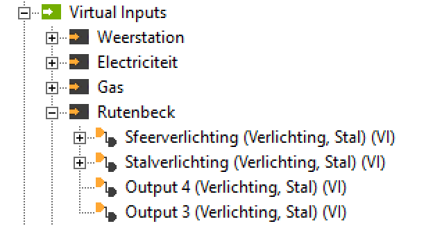
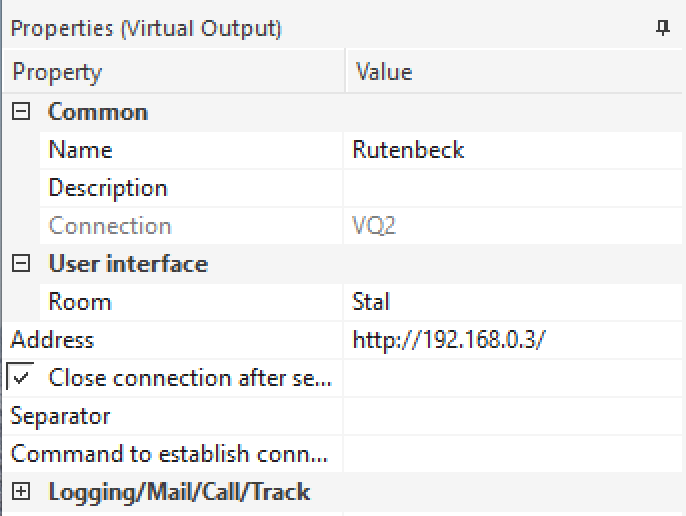
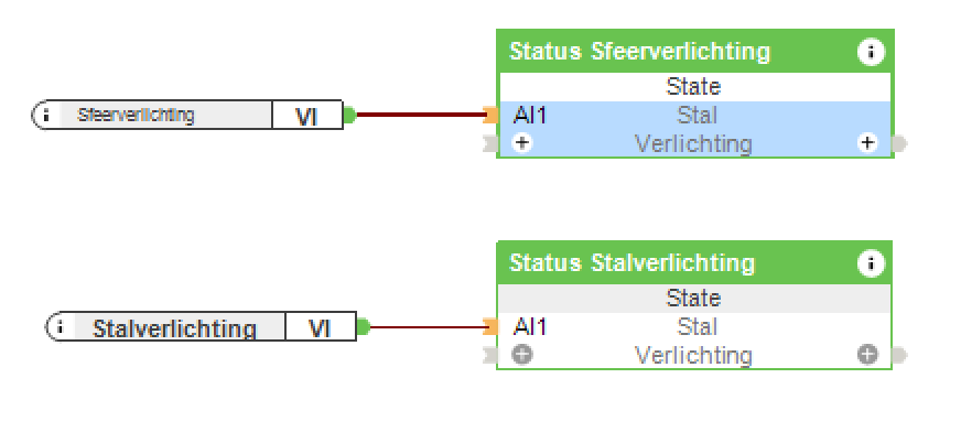
First define two virtual devices, one input and one output. Then create the appropriate ports for each of the relays to be used. See the diagrams below.
You can add the virtual outputs to light controllers, and the inputs to the user interface.
Virtual Input Virtual Input Command Virtual Inpur Status of Led 1 Virtual Output Virtual Output Command Virtual Output Control of Led 1 Light Status Block