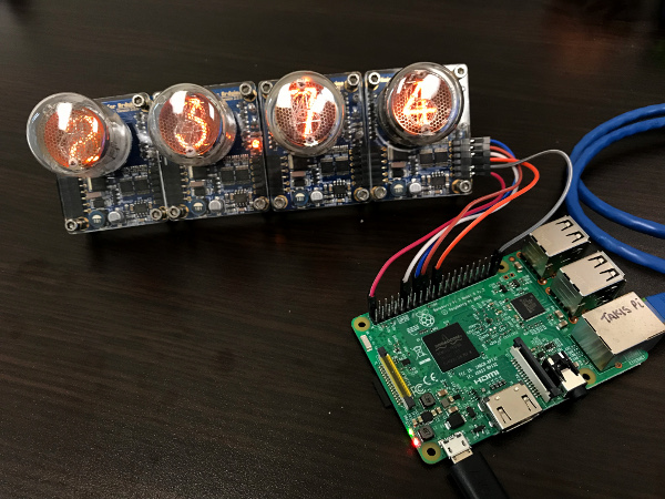
Python module to drive 74HC595 based Nixie modules using Raspberry Pi.
Other Raspberry Pi projects drive an Arduino board which drives the Nixie module. PiNixie drives the Nixie module directly for simplicity.
These Nixie modules are plentiful on Ebay, Amazon, etc. and are typically called "Arduino compatible". They make it easy for the maker because the high-voltage boost circuit and serial to parallel conversion is built in. By using a 74HC595 or similar shift register, a (nearly) unlimited number of digits can be controlled with 4 GPIO pins of the Raspberry Pi.
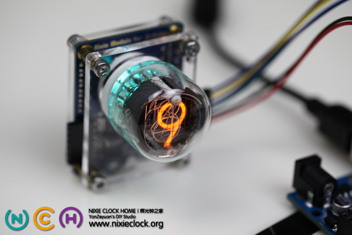
This module was written using the QS30-1 from nixieclock.org as a reference. This module is stackable for multipe digits and has an RGB LED backlight.
http://www.nixieclock.org/?p=566

These modules require 4 pins for data transfer. The GPIO are "bit-banged" in software. Because no hardware resources are used (other than basic GPIO output function), any available GPIO on the Raspberry Pi can be used.
The line in the example below defines which GPIO pin is used for what function.
nixie = pi_nixie.PiNixie(pinDATA=25, pinSHCP=23, pinSTCP=24, pinOE=18)
- pinDATA -- serial data for 74HC595
- pinSHCP -- 74HC595 shifts serial data on rising edge
- pinSTCP -- 74HC595 stores data on rising edge
- pinOE -- high turns on display and backlight, off turns off display and backlight
Note that pinOE is also used for adjusting the brightness of the digits and the backlight LEDs by PWM of the pinOE signal.
The numbers correspond to the GPIO number and not the actual pin number of the header connector. See the documentation for RPi.GPIO for details.
The Raspberry Pi uses 3.3V logic, but the "Arduino compatible" Nixie modules use a 74HC595 shift register IC that is powered at 5V and, technically, should be driven with 5 Volt logic. 3.3 Volts does not meet the 74HC595 datasheet minimum for a logic "1" (Vih). However, in tested HW, it works fine.
If you want to meet all technical requirements for a very robust design, you can use a 3.3V to 5V level shifter such as a 74HC125.
import pi_nixie
nixie = pi_nixie.PiNixie(pinDATA=25, pinSHCP=23, pinSTCP=24, pinOE=18)
nixie.set_brightness(50)
Assuming you had 5 modules (digits), this:
nixie.set_nixie('m8.9 g2:3')
would display "8.9" with magenta background, a space, and "2:3" with a green background.
Supported colon characters are ":", ".", and "`". Use "`" to display just the upper dot in the colon.
The backlight LED color is set by inserting a color character in the string:
- r -- Red
- g -- Green
- b -- Blue
- c -- Cyan
- m -- Magenta
- y -- Yellow
- k -- Black (LED off)
- w -- White
-
The digits to the left are not updating and have the old value
You have to always send the number of numeric digits or SPACE characters to match the number of modules in your string. If you have 4 digits, then always send 4 numeric digits (or SPACE). pi_nixie does not know how many digits you have.
For example, if the nixie display has four digits showing "12:34" and you want to now display ":00", you must send the string as " :00" (2 spaces in front) otherwise the "12" will remain on the left side.
-
Why does the brightness go up when the program stops?
The PWM on pinOE is done using SW via the RPi.GPIO module. When pi_nixie is stopped, pinOE is set to logic high so the display stays on. This also has the effect of setting the backlight LED and digit to full brightness.
-
What PWM frequency
100 Hertz is hard-coded in the module. Move this to a parameter if you want to make it variable.
You can find other projects I've worked on on my blog at http://vince.patronweb.com
