This library controls a Digilent Analog Shield connected to an Arduino from Python over serial. There are three layers to the system: the Arduino side (which controls the Analog Shield), the Python side (which is what is exposed to the user), and the serial protocol that communicates between the two.
-
Upload
analog_shield.inoto the Arduino -
Determine the serial port of the Arduino
- Check the Arduino application
- Mac/Linux only:
$ find /dev -name 'ttyUSB*' -o -name 'ttyACM*' -o -name 'ttyAMA*' -
Use the library:
>>> import AnalogShield as AS
>>> a = AS.AnalogShield("/dev/analog_shield_port") # Connect to the shield
>>> a.ramp_on(0) # Ramp on DAC 0
>>> a.ramp_amplitude(0, 3.3) # Set the amplitude of the ramp to 3.3V
>>> a.analog_read(2, 3) # Take 3 samples of ADC 2
[0.32415, 0.314525, 0.328846]
>>> a.analog_write(3, -2) # Set DAC 3 to -2V
In example code throughout this document, I will use the variable
ato indicate an initializedAnalogShieldobject andASto indicate the module itself.
- Clone the repository:
$ git clone https://github.com/wecassidy/AnalogShield.git - Upload
analog_shield.inoto the Arduino - Install dependencies (NumPy and PySerial):
$ pip install numpy pyserial - Connect the Python library to the shield:
>>> import AnalogShield as AS
>>> a = AS.AnalogShield("/dev/analog_shield_port")
All the code to control the Analog Shield is wrapped in the class
AnalogShield. The code is compatible with both Python 2 and 3
(tested on 2.7 and 3.6) and depends on NumPy (used to calibrate the
ADCs and DACs) and PySerial (to communicate with the Arduino).
Any method that requires a channel expects it to be either an integer
or the string "all". Unless otherwise specified, "all" applies the
method to all channels. In places where there is no reasonable
behaviour for all channels (e.g. reading ADC), "all" is not a valid
value for the channel. This will be noted in the documentation for
that method.
The initializer for the AnalogShield class has one mandatory
argument and one optional one. The mandatory argument is the serial
address of the shield. On Linux systems, this will be something like
/dev/tty*. The optional parameter is the path of a calibration file
for the DACs and ADCs. If it is not provided, the analogue IOs will be
uncalibrated and future calibrations will not be saved. If it is
provided but the file doesn't exist, the analogue IOs will still be
uncalibrated but future calibrations will be saved. If the file
exists, any saved calibrations will be loaded and future calibrations
will be saved to the same location. If, for some reason, you want to
specify the calibration file after the initializer, do it by setting
the calibration_location property of the shield object. See the
section on calibration below for more information on the process.
The primary task of the initializer is to open up serial
communications with the Arduino. The baud rate is 2 Mbps, in
accordance with the serial specification. The timeout of the serial
device is set to 0, meaning that Serial.read() will always return
whatever is in the input buffer and exit immediately. The initializer
also sets up the shield in a known default state.
Summary of the actions the initializer performs:
- Initialize serial communications
- 2 Mbps baud rate
- Set timeout to 0
- Pause for 3s because it fixed some bugs
- Initialize ramp with known settings
- Enabled: no
- Period: 100ms
- Amplitude: 5V
- Offset: 0V
- Phase shift: none
- Shape: triangle
- Load calibrations, if provided
- Turn off queue mode
- Set all DACs to 0V
- For some reason, the first readings from each ADC were sometimes
0x0000,0x0000,0x00**. To fix this, take five samples on each channel
This method sets the value of one of the DACs. Voltage is expected as
a float. If the optional parameter correct is True, the method
will apply the correction function that was determined when the DAC
was calibrated (see the section on calibration for details on that
process). If the DAC hasn't yet been calibrated, a warning will be
printed.
Example use:
>>> a.analog_write(2, -3.5) # Set channel 2 to -3.5V
>>> a.analog_write(0, 4.1, correct=False) # Set channel 0 to 4.1V while suppressing error correction
>>> a.analog_write("all", 0) # Set all channels to 0VThis method takes a number of samples (default 1) as fast as possible
from the ADC, then returns them as a list of floats. This function
cannot be applied to all channels simultaneously, so "all" is not a
valid channel. If the optional parameter correct is True and the
ADC has been calibrated, the correction function will be applied to
the measured voltages (see the section on calibration for details on
that process). If the ADC hasn't yet been calibrated, a warning will
be printed.
Since the ADC samples as fast as possible, a large number of samples can be taken and then averaged to reduce error from a noisy signal. The Arduino runs significantly faster than the Python code, so taking several samples is not significantly slower than taking just one.
Example use:
>>> a.analog_read(1) # Poll channel 1 once
[1.1452345116]
>>> a.analog_read(3, 5) # Take five samples from channel 3
[-0.453614561, -0.5243512614, -0.4123516421, -0.4714526141, -0.5123161424]The Analog Shield can output ramps on each DAC channel in parallel. There are three available ramp shapes: triangle, sine, and square. Ramp amplitude, period, offset, and phase shift can all be set for each channel. Ramps are in phase unless set out of phase with a phase shift.
Ramps that exceed the range of the DACs are clamped to ±5V by the Arduino.
Returns True if a ramp is running on the given channel. If the
channel is "all", this will only return True if ramps are enabled
on all channels.
Enables ramping on the given channel with the current settings.
Disables ramping on the given channel.
Set the period of the ramp, in milliseconds. If a new period is not provided, the current value is returned.
Example use:
>>> a.ramp_period(1, 100) # Set channel 1's period to 0.1s (10Hz)
>>> a.ramp_period("all", 31) # Set all periods to 31ms (~32Hz)
>>> a.ramp_period(3) # Query channel 3's period
12
>>> a.ramp_period("all") # Query all periods
[12, 197, 2632, 1]Set the amplitude of the ramp, in volts. The amplitude of the ramp is the difference between the maximum and average voltages. Consequently, it must be positive. If a new amplitude is not provided, the current value is returned.
Example use:
>>> a.ramp_amplitude(0, 0.14) # Set the amplitude of channel 0 to 0.14V
>>> a.ramp_amplitude("all", 3.14) # Set all amplitudes to 3.14V
>>> a.ramp_amplitude(2) # Query channel 2's amplitude
3.3
>>> a.ramp_amplitude("all") # Query all amplitudes
[1, 5, 3.3, 2]Set the offset of the ramp, in volts. If a new offset is not provided, the current value is returned.
Example use:
>>> a.ramp_offset(3, -4.2) # Set the offset of channel 3 to -4.2V
>>> a.ramp_offset("all", -2.1) # Set all offsets to -2.1V
>>> a.ramp_offset(0) # Query the offset of channel 0
3.3
>>> a.ramp_offset("all") # Query all ramp offsets
[0, 5, -2, 4.21]Set the phase shift of the ramp, as a percentage of the period. For example, if a ramp with a period of 100ms is given a phase shift of 10%, it will be offset 10ms. If a new phase shift is not provided, the current value is returned.
Example use:
>>> a.ramp_phase(2, 50) # Set the offset of channel 2 to 50%
>>> a.ramp_phase("all", 12.5) # Set the phase of all channels to 12.5%
>>> a.ramp_phase(1) # Query the phase of channel 1
75
>>> a.ramp_phase("all") # Query all phase shifts
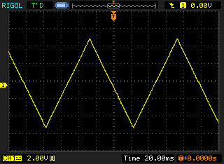
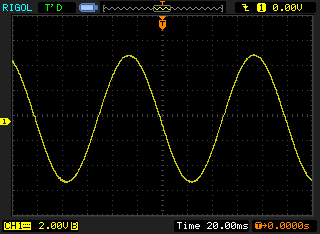
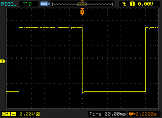
[30, 10, 50, 90]Set the waveform of the ramp to one of three supported shapes: triangle, sin, or square. For information on how these shapes are defined, see the section on ramping in the documentation of the Arduino program. If a new function is not provided, the current value is returned.
Here are what the three ramp functions look like (at amplitude 5V, offset 0V, and period 100ms). From left to right: triangle, sine, square.
Example use:
>>> a.ramp_function(2, "sin") # Use a sine ramp on channel 2
>>> a.ramp_function("all", "square") # Set all channels to a square ramp
>>> a.ramp_function(1) # Query the waveform of channel 1
"triangle"
>>> a.ramp_function("all") # Query all ramp functions
["triangle", "triangle", "sin", "square"]For some reason, the DACs and ADCs that the Analog Shield uses have a linear error, as can be seen in these graphs (DAC on the left, ADC on the right):
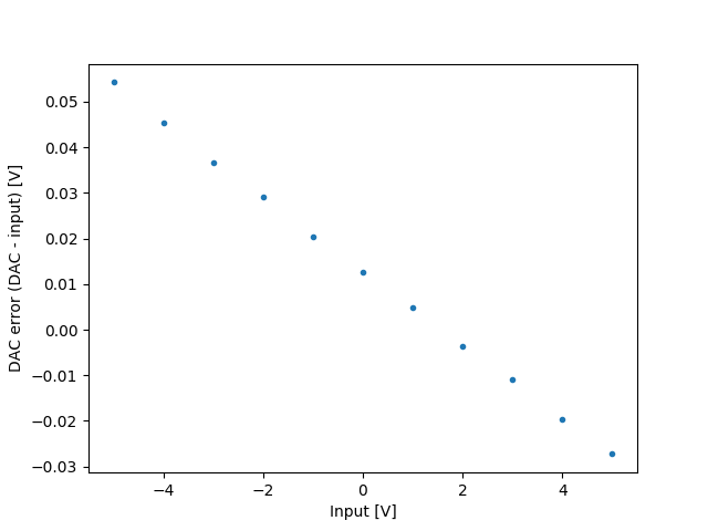
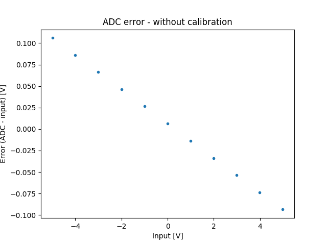
Because the error is a linear function of the input/output voltage (for the DACs and ADCs, respectively), it is easy to take the nominal input/output voltage and actual input/output voltage and calculate a function that reverses the error.
The Analog Shield library provides two functions to automatically
perform the calibration process, one for the DACs and one for the
ADCs. Both require a multimeter that has a Python interface be
connected to the computer. All that is required of the interface is that it
has a method voltage() that returns a number. If the method is named
something else, then it can be aliased by using the following code:
multimeter.voltage = multimeter.other_methodCalibration is specific to each DAC and ADC channel. This means that if you want to calibrate all four of each, you will have to run the calibration methods eight times. A channel can be recalibrated at any time by rerunning the calibrate function on that channel.
The error function seems to be fairly steady over time. To avoid
having to recalibrate the input and outputs every time the shield is
used, the correction functions will be saved to the hard drive using
the pickle module if a calibration file was provided (either in the
initializer or by later setting the value of the attribute
calibration_file).
The calibration functions work by measuring the error (actual - nominal) in 1V steps from -5V to +5V, then using NumPy's polynomial
fitting function to generate a linear function that reverses the
error.
To set up, connect DAC 0 to both the desired ADC and the multimeter. When the function is called, it follows the following algorithm:
- Start at -5V
- Write voltage to DAC 0
- Read multimeter value
- Sample ADC 500 times and take the mean to reduce error due to noise
- Increase by 1V and go to step 2
- Generate error compensation function
- If the calibration file is provided, update it with the new calibration function
Example use:
>>> multimeter = HypotheticalSerialMultimeter("/dev/multimeter")
>>> multimeter.voltage()
1.42345
>>> a.adc_calibrate(0, multimeter) # Calibrate ADC 0To set up, the DAC to the multimeter. When the function is called, it follows the following algorithm:
- Start at -5V
- Write voltage to DAC, suppressing any existing error correction
- Read multimeter value
- Generate error compensation function
- Increase by 1V and go to step 2
- If the calibration file is provided, update it with the new calibration function.
Example use:
>>> multimeter = HypotheticalSerialMultimeter("/dev/multimeter")
>>> multimeter.voltage()
2.489735
>>> a.dac_calibrate(2, multimeter) # Calibrate DAC 2In queue mode, the Arduino waits for an external trigger before
executing commands. This allows for more precise timing. However, as
it is currently written the write method blocks until the command
completes, so execution of the program will hang if a command in queue
mode is not triggered for a long time.
There are two methods related to queue mode: queue_on() and
queue_off(). As the names suggest, they enable and disable queue
mode, respectively. Note that a queue mode off command won't execute
until triggered, just like all other commands in queue mode.
Users shouldn't have to touch these methods, but they are documented here for completeness.
This method writes a command to the Arduino, following the serial specification (see below). Its first parameter is the two-character identifier of the command, and the second is the argument of the command. It returns the response from the Arduino, which is an arbitrary-length string.
This method can be broadly divided into two steps: writing the command, then reading the response.
The command is written as a series of four bytes: first the two-character identifier, then the two-byte argument in big-endian order (MSB first).
The method needs to perform some trickery to ensure that the code
works for a command that is either a bytestring (the default in Python
2) or a Unicode string (the default in Python 3). To this end, it
first converts the identifier and argument into a four-byte
bytearray, where the four bytes are [first character, second character, MSB, LSB]. This bytearray is written to the serial port.
According to the serial protocol, responses are always terminated by a
semicolon (;). Because of this, the method simply consumes bytes
from the serial port until it reads a semicolon. Unfortunately,
Serial.read() returns a bytes object, whose behaviour differs
between Python 2 and 3. The check for a semicolon works by slicing the
last character off the response so far. In Python 2, bytes and str
are exactly the same thing (bytes is str is True), and slicing a
bytes gives a string. Meanwhile, Python 3's bytes is a distinct
type, and slicing it gives a number. Therefore, two checks are
required: either the last entity in the response must be the string
";" (Python 2) or the number 0x3b (Python 3), which is the ASCII
code for semicolon.
The method must ensure that it returns a Unicode string in Python 3,
to avoid unexpected bugs for the end user. Therefore we decode the
response using the Latin-1 encoding (which is back-compatible with
ASCII while leaving the possibility of using characters \x80-\xff
for future versions of the program, and each byte corresponds to a
single character).
The closing semicolon is required for effective operation of the serial protocol but adds no value or information to the response once read, so it is stripped before the response is returned.
There are two functions volts_to_bits(volts) and
bits_to_volts(bits) that convert a number from volts to bits in the
Analog Shield format (see the Serial Protocol section for details) and
vice versa. These two functions are static methods, so they should be
called as:
>>> AS.AnalogShield.bits_to_volts(0xd47a)
3.2999923704890524
>>> AS.AnalogShield.vots_to_bits(-2.5)
0x3fffThis static method separates a two-byte number into individual bytes,
then returns them in a list. The bytes are in big-endian (MSB first)
order. Obtaining the two separate bytes are simple bitwise
operations. To get the most significant byte, shift the number right
eight bits, discarding the rightmost ones. To get the least
significant byte, perform a bitwise AND operation with 0x00ff,
setting the MSB to zero while leaving the other byte untouched. Here's
what it looks like in binary:
Input number: 0100 1111 0010 1011

MSB: 0100 1111 0010 1011 >> 8 = 0100 1111
LSB: 0100 1111 0010 1011 & 0000 0000 1111 1111 = 0010 1011
Example use:
>>> AS.AnalogShield.encode_num(1234) # 1234 = 0x04d2
[4, 210] # [0x04, 0xd2]
See also "Converting the argument" in the Arduino section for the reverse process.
Basic flow of the Arduino program:
- Read whatever is available in the serial in buffer
- If the command is fully received, process it
- Split the command into identifier (first two characters) and argument
- Convert the argument from two bytes into an unsigned short
- Run the ramp
Each group of commands (based on first character) has its own function that processes the specific command and the argument. They return a status code to determine successful execution (zero for success, nonzero for an error).
We want to go from two separate bytes (for example, 0x4f and 0x2b)
to one two-byte number (0x4f2b). To do this, shift the first byte
left eight bits and add the second byte. Here's what the process looks
like in binary:
Input bytes: 0100 1111, 0010 1011

Step 1: 0100 1111 << 8 = 0100 1111 0000 0000
Step 2: 0100 1111 0000 0000 + 0010 1011 = 0100 1111 0010 1011
Each ramp shape is defined as a function of time since the Arduino started executing (in microseconds to be as correct as possible). This has a few consequences:
- Ramps with the same period are in phase
- It's very easy to add another ramp shape, simply define another ramp function
- There will be a discontinuity when the microseconds counter rolls over (approximately 70 minutes after the program starts)
The ramping code works by calculating the voltage at the current time using the ramp function, then clipping if it goes out of range.
These are the functions that define the various ramps:
- Triangle:
V(t) = amplitude * (|(t - phase shift) % period - period/2| / (period/4) - 1) + offset - Sine:
V(t) = amplitude * sin(2π/period * (t - phase shift)) + offset - Square:
V(t) = amplitude * (-1)^floor((t - phase shift) / period) + offset
New ramp functions should have a range of [-1, 1] when amplitude is 1V and offset is 0V to work as expected.
The protocol works on a command-response basis: the Python side sends a command, then blocks until the Arduino finishes executing the command and returns a response.
The format of the command is simple: each command is exactly four
bytes in length. The first two bytes are the identifier of the
command, which consists of two ASCII characters. Commands are
case-insensitive, so the commands RO, Ro, rO, and ro are all
equivalent. The next two bytes consist of the argument. How it is
formatted is specific to each command. It may be interpreted as a
16-bit integer, it may be ignored, or it may be used another way
entirely. Commands which have similar functions are grouped by having
the same first character. Voltages are always communicated using the
bit format used by the Analog Shield library (i.e. 0x0000
corresponds to -5V and 0xffff corresponds to 5V).
The response is an arbitrary number of ASCII characters terminated by
a semicolon (;, ASCII 0x3b). If the command completes successfully
with no other response required, it will return OK;. If an error
occurs at any time, whether in parsing or executing the command, the
response will be ??;.
The serial protocol operates at a baud rate of 2 Mbps to reduce communication latency.
Each channel can output a ramp in parallel. The ramp period, amplitude, offset, phase shift, and waveform are all individually configurable.
Default settings:
- Ramp off
- Period: 100 milliseconds
- Amplitude: 0V
- Offset: 0V
- Phase shift: none
- Function: triangle
| Command | Identifier | Argument | Function |
|---|---|---|---|
| Channel select | rc |
Channel number | Choose the channel which future r* commands will adjust. |
| Ramp on | r1 |
Ignored | Enable ramping on the currently selected channel. |
| Ramp off | r0 |
Ignored | Disable ramping on the currently selected channel. |
| Period | rp |
Period in milliseconds | Set the period of the ramp function. The argument is interpreted as a two-byte unsigned integer, so the range of possible values is 1ms to 65.535s in 1ms increments (0.015Hz to 1kHz). |
| Amplitude | ra |
Voltage in Analog Shield format (0x0000 = -5V, 0xffff = 5V) |
Set the amplitude of the ramp function (amplitude is Vaverage to Vmax, not Vpp). If the ramp goes out of the range of the DACs (±5V), the waveform will be clipped. |
| Offset | ro |
Voltage in Analog Shield format (0x0000 = -5V, 0xffff = 5V) |
Set the offset of the ramp function (Vaverage). If the ramp goes out of the range of the DACs (±5V), the waveform will be clipped. |
| Phase shift | rs |
Percentage of a period (0x0000 = 0%, 0xffff = 100%) |
Set the phase shift of the ramp function relative to the period. For example, a 25% phase shift on a 50ms period results in a 12.5ms phase shift. |
| Function | rf |
0: triangle; 1: sine; 2: square | Set the waveform of the ramp. |
| Command | Identifier | Argument | Function |
|---|---|---|---|
| Single channel | vN (N is the DAC channel) |
Voltage in Analog Shield format (0x0000 = -5V, 0xffff = 5V) |
Set a single DAC to output constantly at a given level. If there is a ramp running on that channel, the ramp will be turned off. |
| All channels | va |
Voltage in Analog Shield format (0x0000 = -5V, 0xffff = 5V) |
Set all DACs to output constantly at the given level. |
| Command | Identifier | Argument | Function |
|---|---|---|---|
| Read voltage | aN (N is the ADC channel) |
Number of samples | Sample an ADC n times as quickly as possible. Returns all the readings as a series of comma-separated hex numbers (the voltages in Analog Shield format). |
Queue mode enables more accurate timing of commands. Instead of executing commands immediately when it receives them, queue mode stores commands in the serial input buffer and waits until the queue pin (pin 7) is brought high to execute.
| Command | Identifier | Argument | Function |
|---|---|---|---|
| Toggle queue mode | qm |
0: off; 1: on | Enable or disable queue mode. |