
- -55 to 0 dBm RF power measurement up to 10 GHz
- 2-point calibration (linear function), separate for each band
- Measuring
average,max(peak) andminpower. - Ability to use an external RF attenuator
- Headless mode - control over serial only
- Display power in dBm, mW or W
- External attenuator support - 0..60 dB in 10 dB steps
- Arduino Nano
- AD8317 power meter module
- SSD1306 128x32px OLED display
- LM4040 reference voltage (2.048 V)
- Build and flash Arduino software
- Build a voltage reference and connect it to
AREFpin of Arduino, VCC (5V) and GND.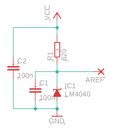
- Connect AD8317 module output to
A0pin of Arduino, connect the grounds together. Provide 5V to the module. - Connect OLED display to VCC, GND & SDA (
A4), SCL (A5) Arduino pins. - Connect buttons to pins D9 and D10. They should short pins to GND when pressed, internal pullup is used. GND is also available on D8.

- Power the meter while pressing a button
- "CALIB" should appear on the screen, raw ADC value will be displayed
- Select band and averaging, as well as current generator level (-40 or -10 dBm by default)
- Select "SAVE" and click SET button to save the calibration value to EEPROM
- To make sure the calibration has been saved correctly, open serial port (115200 bps) and send "p" letter to the meter
- Table with raw calibration values will be printed via serial terminal
- Add buttons [done]
- Show power also in mW/W [done]