AIME Reader & Bandai Namco Reader & Cardio Emulator

Features:
- It's small, smallest as far as I know.
- Many variants
- AIC Pico (PN532)
- AIC Pico (PN5180, no housing)
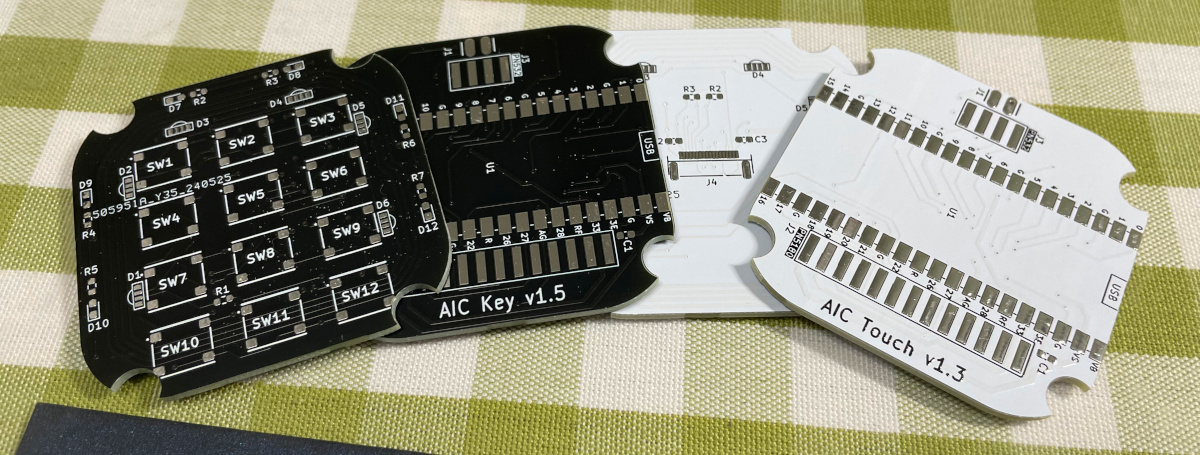
- AIC Key PN532/PN5180
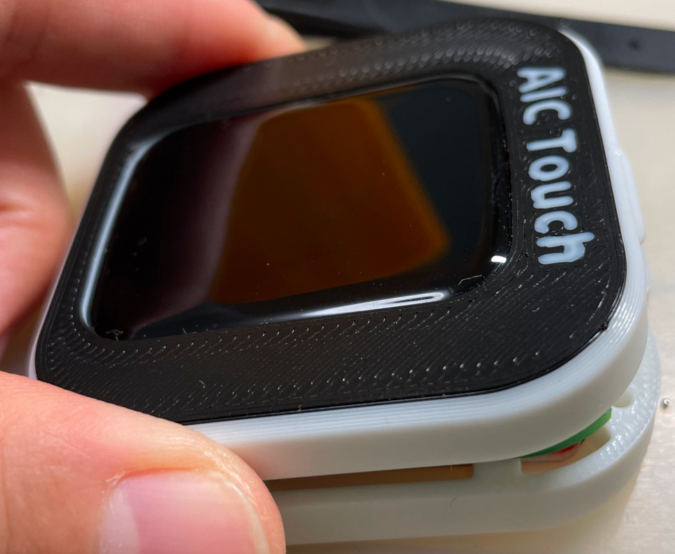
- AIC Touch PN532/PN5180
- AIC Pico Lib (see notes 1 below)
- Easy to make.
- Sega AIME I/O, Bandai Namco I/O and Spicetools CardIO emulation.
- Automatic detection of I/O protocols above.
- Command line for configurations.
- Supported card:
- FeliCa (Amusement IC)
- ISO/IEC 14443 Type A (BanaPassport, Mifare, Amiibo, some IC tags, some ID tags, etc.)
- ISO/IEC 15693 (Old E-Amusement cards), only with PN5180 (see notes 2 below)
- Emulates virtual AIC from any Mifare cards (not for Bandai Namco I/O).
- All source files open.
Notes:
- So one can integrate "AIC Pico" into other Raspberry Pi Pico based projects. See my Chu Pico project and see how it works.

- PN532 supports only 14443A (Mifare) and FeliCa cards, while PN5180 also supports 15693 cards (old e-Amusement cards).
Thanks to many respectful guys/companies who made their tools or materials free or open source (KiCad, OnShape, InkScape, Fritzing, Raspberry things), ChatGPT and GitHub Copilot helped a lot as well.
And thanks to community developers and projects that helped me a lot:
- CrazyRedMachine (https://github.com/CrazyRedMachine) for the Spicetools Card IO part;
- Sucareto's AIME Reader (https://github.com/Sucareto/Arduino-Aime-Reader) for the AIME protocol part;
- Bottersnike (https://gitea.tendokyu.moe/Bottersnike, https://sega.bsnk.me/) for AIME and FeliCa knowledge;
- .NET nanoFramework (https://github.com/nanoframework) for the PN5180 part;
- Gyt4 (https://github.com/gyt4/) for Bandai Namco card reader I/O;
- Bananatools (https://gitea.tendokyu.moe/Hay1tsme/bananatools) for Bandai Namco card reader I/O;
- chujohiroto (https://github.com/chujohiroto/Raspberry-RCS620S/blob/master/rcs620s.py), as indirect reference for the Bandai Namco card reader I/O;
This project:
- Heavily depends on 3D printing, a Bambu AMS system helps a lot.
- Requires skills to solder tiny components and wires.
You can check out my other cool projects.


- Popn Pico: https://github.com/whowechina/popn_pico
- IIDX Pico: https://github.com/whowechina/iidx_pico
- IIDX Teeny: https://github.com/whowechina/iidx_teeny
- Chu Pico: https://github.com/whowechina/chu_pico
- Mai Pico: https://github.com/whowechina/mai_pico
- Diva Pico: https://github.com/whowechina/diva_pico
- AIC Pico: https://github.com/whowechina/aic_pico
- Groove Pico: https://github.com/whowechina/groove_pico
- Geki Pico: https://github.com/whowechina/geki_pico
- Musec Pico: https://github.com/whowechina/musec_pico
- Ju Pico: https://github.com/whowechina/ju_pico
I made this project in my personal time with no financial benefit or sponsorship. I will continue to improve the project. I have done my best to ensure that everything is accurate and functional, there's always a chance that mistakes may occur. I cannot be held responsible for any loss of your time or money that may result from using this open source project. Thank you for your understanding.
It's CC-NC. So DIY for yourself and for your friend, don't make money from it. And plagiarism that doesn’t even dare to mention the original author is not acceptable. Plase note that pooling orders and group buying for raw materials is acceptable. Selling off any leftover components without profit is also acceptable.
If you're interested in buying from me or for commercial use, please contact me (Discord, QQ group, Wechat group or leave your contact in issue section).
Seriously, this is the easiest one among all my Pico series projects.
- 1x Rasberry Pi Pico or Pico W (clones work too).
https://www.raspberrypi.com/products/raspberry-pi-pico - 1x PN532 Module (the Red Square board version, cheap clones work too).
https://www.elechouse.com/product/pn532-nfc-rfid-module-v4/ - Some thin wires.
- Thin WS2812B LED strip.
- 4x M2*8mm screws.
- aic_pico_bottom.stl
The bottom part.
For the top part, choose one that fits your need.
- aic_pico_top.stl
Regular top part. - aic_pico_top_ams.3mf
Regular top part, multi-color printing. - aic_pico_top_tall.stl
Taller top part, so a thicker LED strip can fit. - aic_pico_top_tall_ams.3mf
Taller top part, multi-color printing.
Top parts should be printed upside-down.

I'll let these images do the talk.


- The firmware supports up to 64 LEDs on the WS2812B LED strip. I personally used 3 as shown in main title image. But you can have different LED number, as long as they fit within the housing.
- LED might be excessively bright even at low settings, consider covering it with some filter tape.
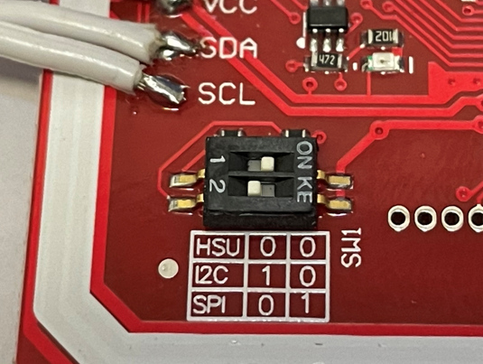
- The mode switch on PN532 must be in "I2C" mode, picture below shows the correct settings.
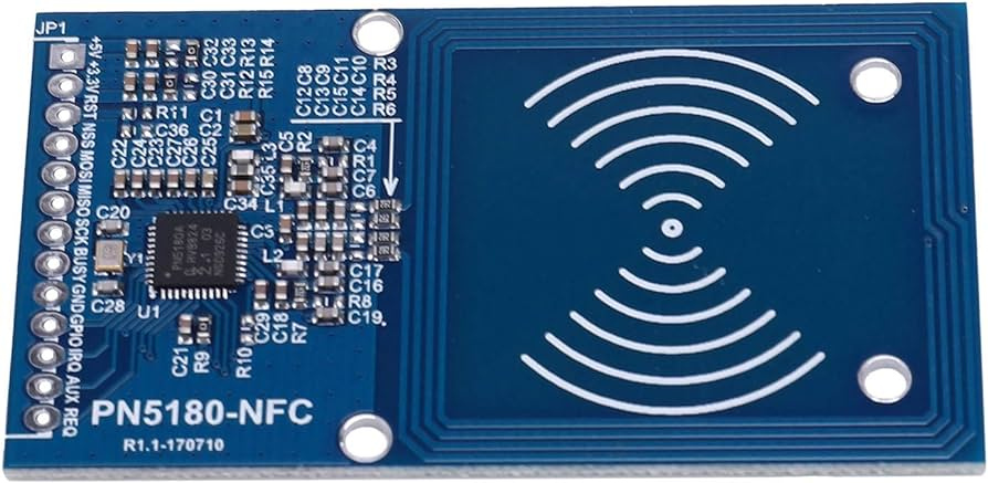
If you opt for the PN5180 NFC module, note that the housing design is up to you. Ensure it fits your design or you can use it without a case. Be prepared to solder more wires compared to the PN532 version.

Note: WS2812B LED Strip wiring is the same as the PN532 version.
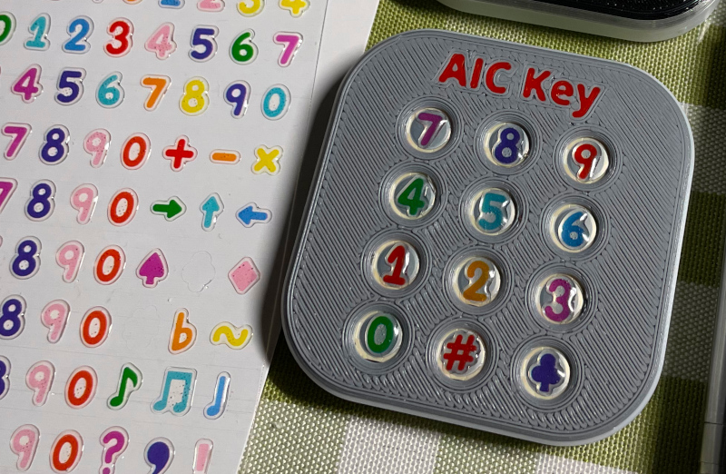
AIC Key is a variation of the AIC Pico - a keypad is integrated. Much more difficult to build than the "AIC Pico" as it has many tiny components to solder.
-
1x Rasberry Pi Pico or Pico W (clones work too).
https://www.raspberrypi.com/products/raspberry-pi-pico -
For NFC modules, choose one of the following options:
- 1x PN532 Module (the red square board version, cheap clones work too).
https://www.elechouse.com/product/pn532-nfc-rfid-module-v4/ - 1x PN5180 Module (the blue rectangle version, cheap clones work too). PN5180 supports ISO/IEC 15693 (old e-amusement cards).
- 1x PN532 Module (the red square board version, cheap clones work too).
-
For LEDs, you also have 2 options:
- Option 1: 6x side-light WS2812B 1204 LEDs (D1 to D6) and a 10ohm 0603 resistor (R1), GREEN mark in the assemble image. (available for both AIC Key and AIC Touch)
- Option 2: 6x regular single-color 0603 LEDs (D7 to D12) and 6x 100ohm 0603 resistors (R2 to R7), PURPLE mark in the assemble image. (available for AIC Key only)
-
C1, C2, C3, 0603 10uF capacitors, they contribute to a more stable power supply.
-
For switches, you still have 2 option:
- Option 1: 12x ALPS SKRRAAE010 low-profile TACT switch.
https://www.mouser.com/ProductDetail/Alps-Alpine/SKRRAAE010?qs=m0BA540hBPeKhAe3239t1w%3D%3D - Option 2: 12x Panasonic EVQP1K05M 6mm square tactile switch.
https://www3.panasonic.biz/ac/e/dl/catalog/index.jsp?series_cd=3473&part_no=EVQP1K05M
- Option 1: 12x ALPS SKRRAAE010 low-profile TACT switch.
-
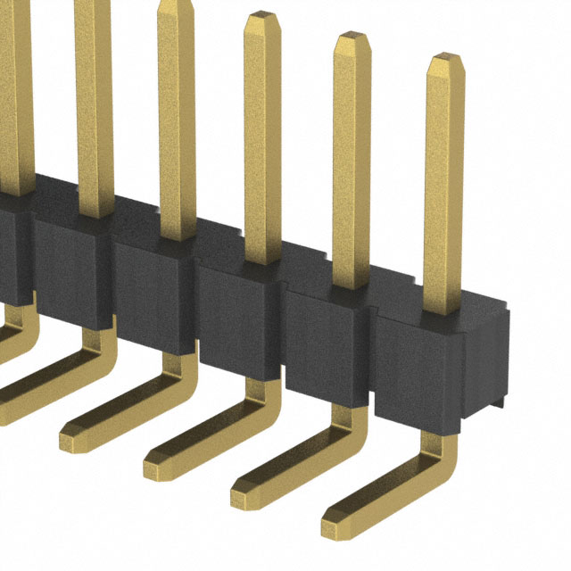
1x Right angle 2.54mm pitch header, 4P for PN532, 13P for PN5180.
-
1x Stickers of numbers. You can find some customize sticker service, or you can find some existing stickers. I found this Bonito crystal 3D stickers super helpful for this project.

-
PCB, visit JLCPCB (https://jlcpcb.com/) and place an order there. Leave everything default, 1.6mm thickness, whatever color you like. The PCB gerber file is "Production/PCB/aic_key_v*.zip".


- aic_key_bottom.stl
Bottom part. - aic_key_top_surface.stl
Top part for Alps surface switches. - aic_key_top_surface_ams.3mf
Top part for Alps surface switches, multi-color printing. - aic_key_top_tact.stl.stl
Top part for Panasonic tact switches. - aic_key_top_tact_ams.3mf
Top part for Panasonic tact switches, multi-color printing.
Top parts should be printed upside-down.
Again I'll let these images do the talk. Remember to upload the firmware onto Raspberry Pi Pico before assemble. Please note, the latest PCB is compatible with both PN532 and PN5180, and you can solder according to your needs. The photos below are based on an earlier version of the PCB and may not correspond exactly, but I believe you will be able to understand.


Remember set to I2C mode first.


CAUTION:
-
There's a possibility that the antenna on the PN532 PCB may come into contact with the USB connector and cause RF problem. To prevent this, you can apply some insulating tape.
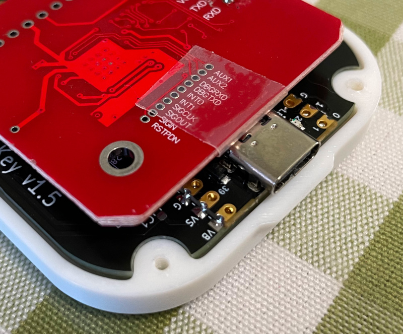
-
Due to manufacturing errors, your PN532 module may not fit perfectly into the housing. If necessary, you can gently trim the edges of the PN532 module for a better fit.

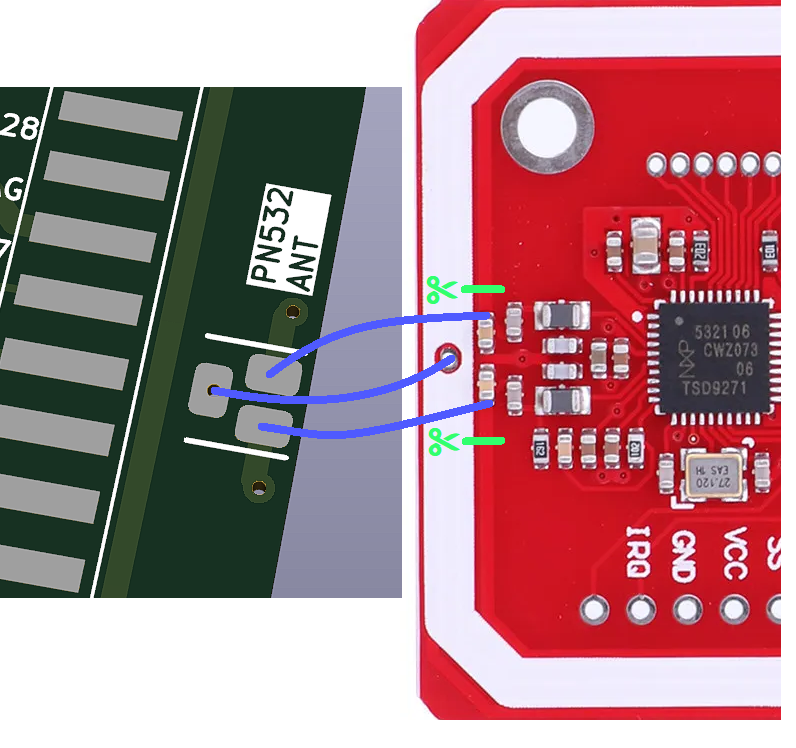
You need to cut off the original antenna and use the one in our PCB.


You may use some instant adhesive to fix stickers.

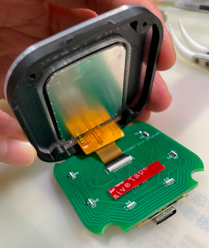
AIC Touch, another variant of AIC Pico, comes with an integrated touchscreen. However, its tiny FPC/FFC connector significantly increases the soldering and assembly difficulty.
-
For the Raspberry Pi Pico, NFC module, 6x WS2812B 1204 LEDs and the R1 resistor part, follow the guide for AIC Key.
-
C1, C2, C3, 0603 0.1uF capacitors, they contribute to a more stable power supply.
-
R2, R3, pull-up resistors for the I2C bus, 0603 1Kohm ~ 4.7Kohm.
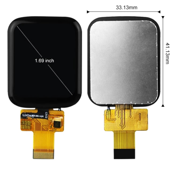
-
1.69 inch 240x280 LCD touchscreen (ST7789 + CST816). Several vendors are making this model, as long as one has the exact same looking, it will be fine. It looks like this.
-
The FPC/FFC flip cover connector for the touchscreen. 18P, 0.5mm Pitch, 1.0H (1mm height), front flip (flip cover at cable side), bottom contact. It looks like this:
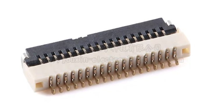
-
PCB file "aic_touch_v*.zip".


- aic_touch_bottom.stl
Bottom part. - aic_touch_top.stl
Top part. - aic_touch_top.3mf or aic_touch_top_ams.3mf
Top part for multi-color printing. The latter is for Bambu Studio with AMS system. Filament 1 is black, Filament 2 is clear transparent.
Top parts should be printed upside-down.
To achieve the best aesthetic results, I recommend using the combination of clear PLA and black PLA. For the top part, make the first 2 layers of the sub-object "Top" black, and all others clear.

For most of the part, just follow the guide of AIC key.
-
The touchscreen will block PN532's RF signal so we need to offload the antenna to AIC Touch's PCB just like what we do in PN5180 version.
- To build PN5180 version, short the "PN532 ANT" (green mark in the picture). To build PN532 version, short the "PN5180 ANT" (red mark in the picture).
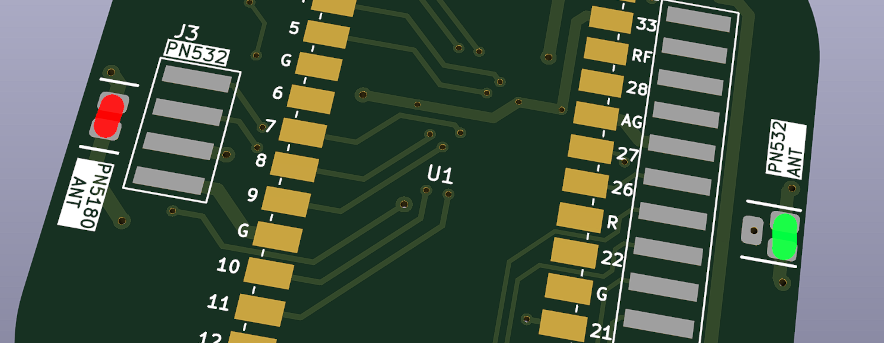
- Not like the PN5180, the PN532 has 3 pins - it has a center tap. Here's how you offload the antenna from the PN532. Cut (with small knife or chisel) the original 2 traces of the antenna (green marks in the picture) and connect 3 "PN532 ANT" pins to the PN532 module.
- To build PN5180 version, short the "PN532 ANT" (green mark in the picture). To build PN532 version, short the "PN5180 ANT" (red mark in the picture).
-
Soldering the 18P-0.5mm-1.0H FPC/FFC connector can be challenging. Here are some tips to make the process easier:
- Use a small, sharp iron tip, the smaller the better.
- Set your soldering iron to a lower temperature, below 280 degrees Celsius.
- Apply a generous amount of high-quality solder flux to keep the pins "wet" during soldering.
- Use thin low-temperature solder wire (for example, diameter of 0.3mm).
- Start by soldering the mounting pins on both sides for proper alignment, then proceed with the 18 main pins.
- Don't feed solder wire directly onto the main pins.
- When soldering main pins, only apply a very small amount of solder to the iron tip.
- If you apply too much solder, a solder wick can be used effectively to remove the excess.
-
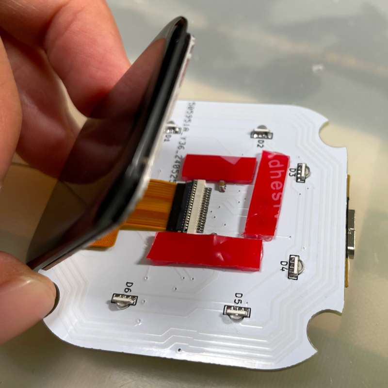
Remember to put 1mm-thick soft pads to support the touchscreen. You can use 1mm 3M VHB double-sided tape, but do NOT remove the red film liner (don't let the tape stick to the touchscreen).
-
Done!


- UF2 file is in
Production\Firmwarefolder. - There're several ways to boot into firmware update mode:
- For the new build, hold the BOOTSEL button while connect the USB to a PC, there will be a disk named "RPI-RP2" showed up. Drag the UF2 firmware binary file into it. That's it.
- If there's already a working firmware, you can use "update" command in command line to update the firmware in the future, so you don't need to open the housing.
- If there's already a working firmware later than 2023-12-02, you can also press "00" key and "·" key (or directly ground the GPIO10 and the GPIO11) at the same time when plug in the USB cable, it will boot into firmware update mode.
- One USB serial port is for command line. You can use this Web Serial Terminal to connect to it. (Note: "?" is for help)
https://googlechromelabs.github.io/serial-terminal/ - The other serial port is for reader protocol, currently SEGA AIME and Bandai Namco are supported.
- Spicetools cardio (Card I/O) HID is always enabled unless a reader protocol is active;
- If your PN5180 module has an issue with Mifare (Such as AIME and Bana Passport) reading, you can try enable the PN5180 TX tweak by "pn5180_tweak on" command.
- Some command line commands:
- "light <rgb|led|both|off>" to turn on or off the LEDs.
- "level <0..255> <0..255>" to adjust the brightness.
- "nfc" manually to detect cards.
- "update" reboot into firmware update mode.
- Given my limited hobby time, the firmware may not be fully tested. Please report any anomalies.
To support many different NFC cards and tags, card IDs are transformed following these rules.
- 15693 => 0x01 + last 7 bytes of UID
- MIFARE (4-byte UID) => 0x01 + 0x01 + UID + first 2 bytes of the UID
- MIFARE (7-byte UID) => 0x01 + UID
- FeliCa => Original IDm
- 15693 => original UID
- MIFARE (4-byte UID) => 0xE0 + 0x04 + UID + first 2 bytes of the UID
- MIFARE (7-byte UID) => 0xE0 + UID
- FeliCa => Original IDm
- MIFARE (4-byte UID) => UID
- FeliCa => Original IDm