Design files of microwave structures used in my researches and projects.
Designed and simulated by CST - Computer Simulation Technology
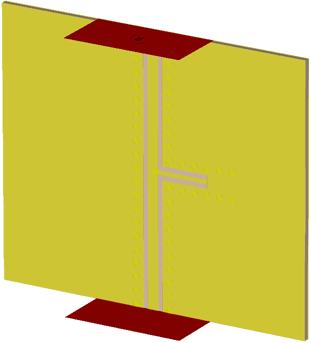
★ Substrate Integrated Waveguide (SIW)
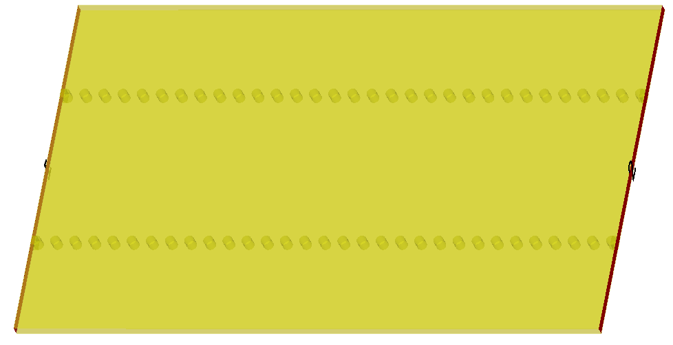
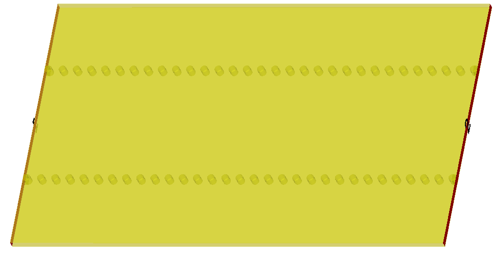
- Design: K-Band Substrate Integrated Waveguide
- Material: 0.01" Rogers RO3003
- File:
Substrate Integrated Waveguide/SIW/Rogers RO3003/SIW_RO3003_KBand.cst
- Figure:
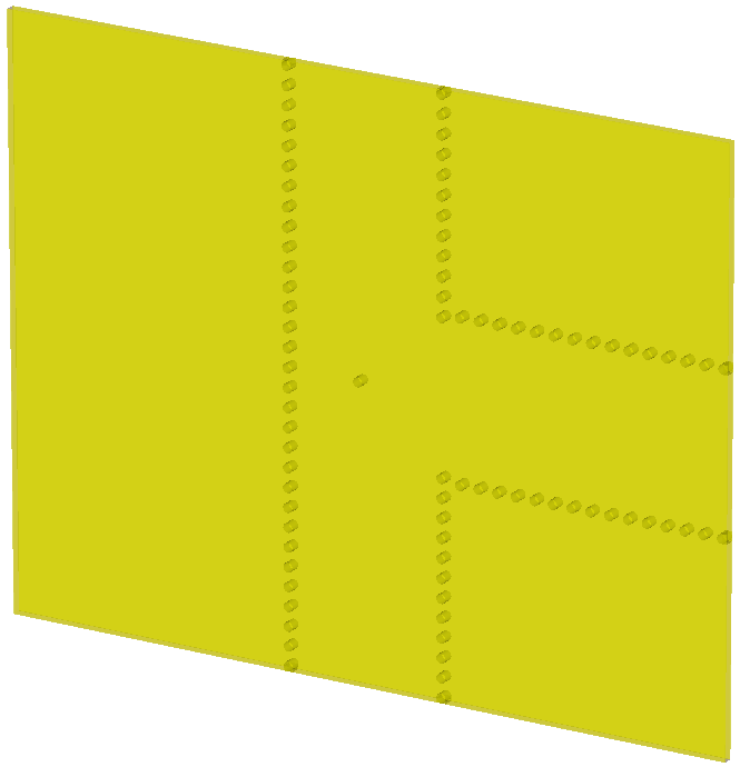
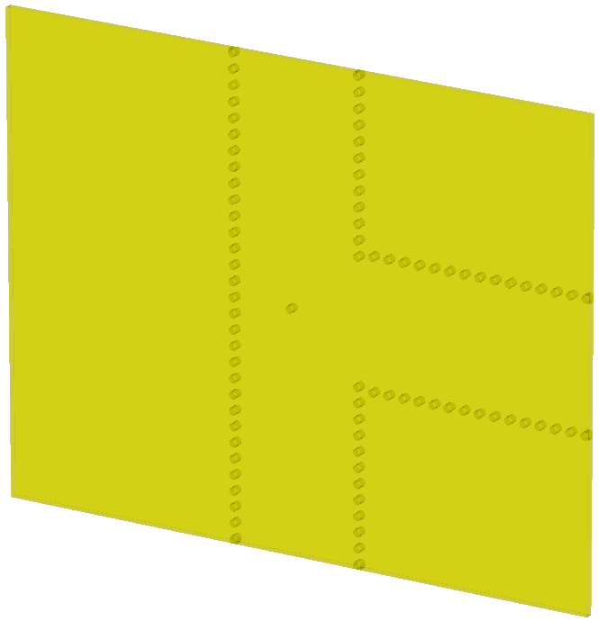
- Design: K-Band SIW Power Splitter
- Material: 0.01" Rogers RO3003
- File:
Substrate Integrated Waveguide/Power Splitter/Rogers RO3003/SIW_Spiliter_RO3003_KBand.cst
- Figure:
★ Coplanar Waveguide (CPW)
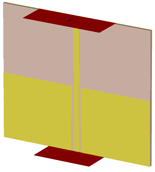
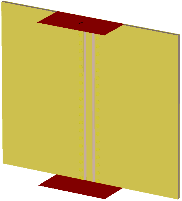
- Design: K-Band Coplanar Waveguide
- Material: 0.01" Rogers RO3003
- File:
Coplanar Waveguide/CPW/Rogers RO3003/CPW_RO3003_KBand.cst
- Figure:
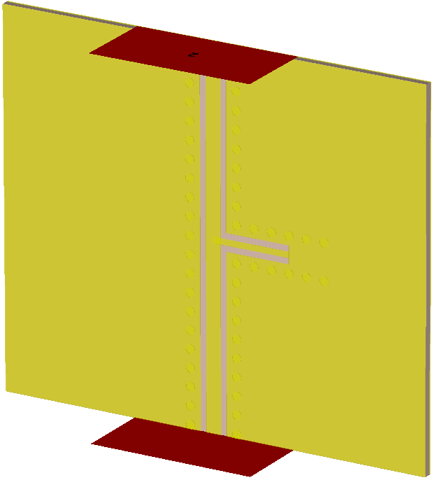
- Design: 24 GHz CPW DC Ground Stub
- Material: 0.01" Rogers RO3003
- File:
Coplanar Waveguide/Ground/Rogers RO3003/DCGround_CPW_RO3003_24G.cst
- Figure:
Microstrip Wilkinson Power Divider
-
Design: 24 GHz 45-Degree Microstrip Turn
- Material: 0.01" Rogers RO3006
- File:
Microstrip/Turns/Rogers RO3006/45DegreeTurn_RO3006_24G.cst
- Figure:

-
Design: 24 GHz 90-Degree Microstrip Turn
- Material: 0.01" Rogers RO3006
- File:
Microstrip/Turns/Rogers RO3006/90DegreeTurn_RO3006_24G.cst
- Figure:

-
Design: 24 GHz 90-Degree x2 Microstrip Turn
- Material: 0.01" Rogers RO3006
- File:
Microstrip/Turns/Rogers RO3006/90DegreeTurnx2_RO3006_24G.cst
- Figure:

-
Design: 24 GHz 90-Degree x4 Microstrip Turn
- Material: 0.01" Rogers RO3006
- File:
Microstrip/Turns/Rogers RO3006/90DegreeTurnx4_RO3006_24G.cst
- Figure:

-
Design: 24 GHz 45-Degree Microstrip Turn
- Material: 0.01" Rogers RT/duroid 5880
- File:
Microstrip/Turns/Rogers RTduroid 5880/45DegreeTurn_RT5880_24G.cst
- Figure:

-
Design: 24 GHz 75-Degree Microstrip Turn
- Material: 0.01" Rogers RT/duroid 5880
- File:
Microstrip/Turns/Rogers RTduroid 5880/75DegreeTurn_RT5880_24G.cst
- Figure:

Microstrip Hybrid Coupler
-
Design: 24 GHz 90-Degree Hybrid Coupler
- Material: 0.01" Rogers RO3006
- File:
Microstrip/Coupler/Rogers RO3006/90Hybrid_RO3006_24G.cst
- Figure:

-
Design: 24 GHz 90-Degree Hybrid Coupler
- Material: 0.032" Rogers RO4350
- File:
Microstrip/Coupler/Rogers RO4350B/90Hybrid_RO4350_24G.cst
- Figure:

-
Design: 24 GHz 90-Degree Hybrid Coupler
- Material: 0.01" Rogers RT/duroid 5880
- File:
Microstrip/Coupler/Rogers RTduroid 5880/90Hybrid_RT5880_24G.cst
- Figure:

-
Design: 24 GHz Rat-Race Coupler
- Material: 0.01" Rogers RT/duroid 5880
- File:
Microstrip/Coupler/Rogers RTduroid 5880/RatRace_RT5880_24G.cst
- Figure:

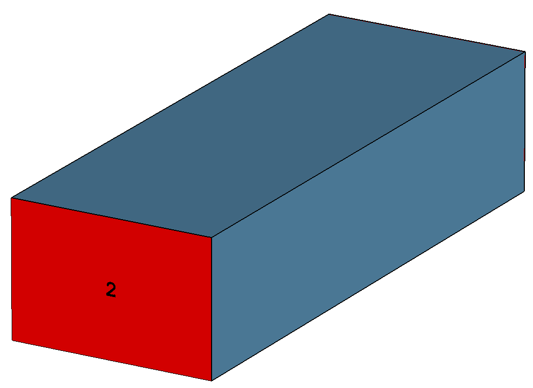
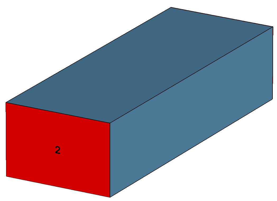
- Design: 14.5 mm x 9.525 mm Straight Waveguide Segment
- Material: PEC and air
- File: Waveguide/Waveguide/WaveguideSegment_11-15G.cst
- Figure:
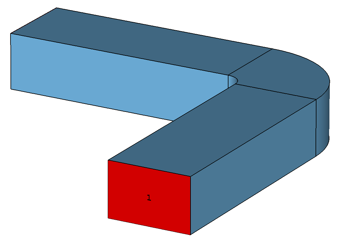
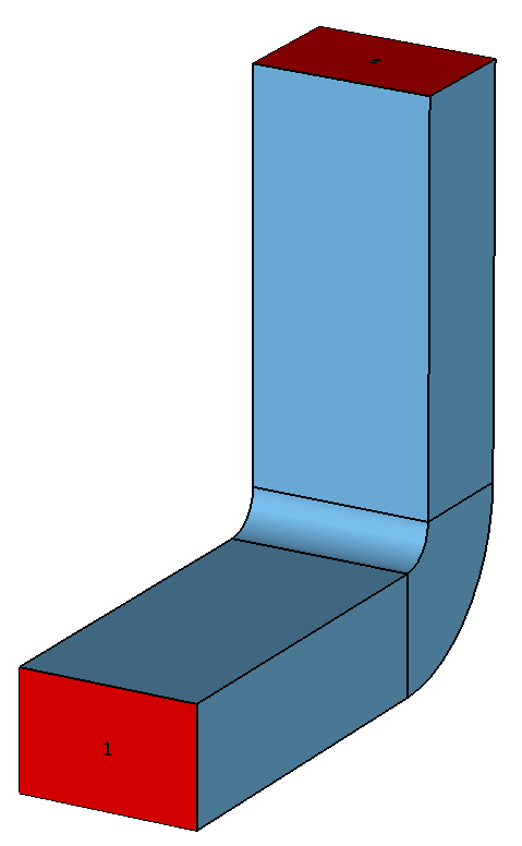
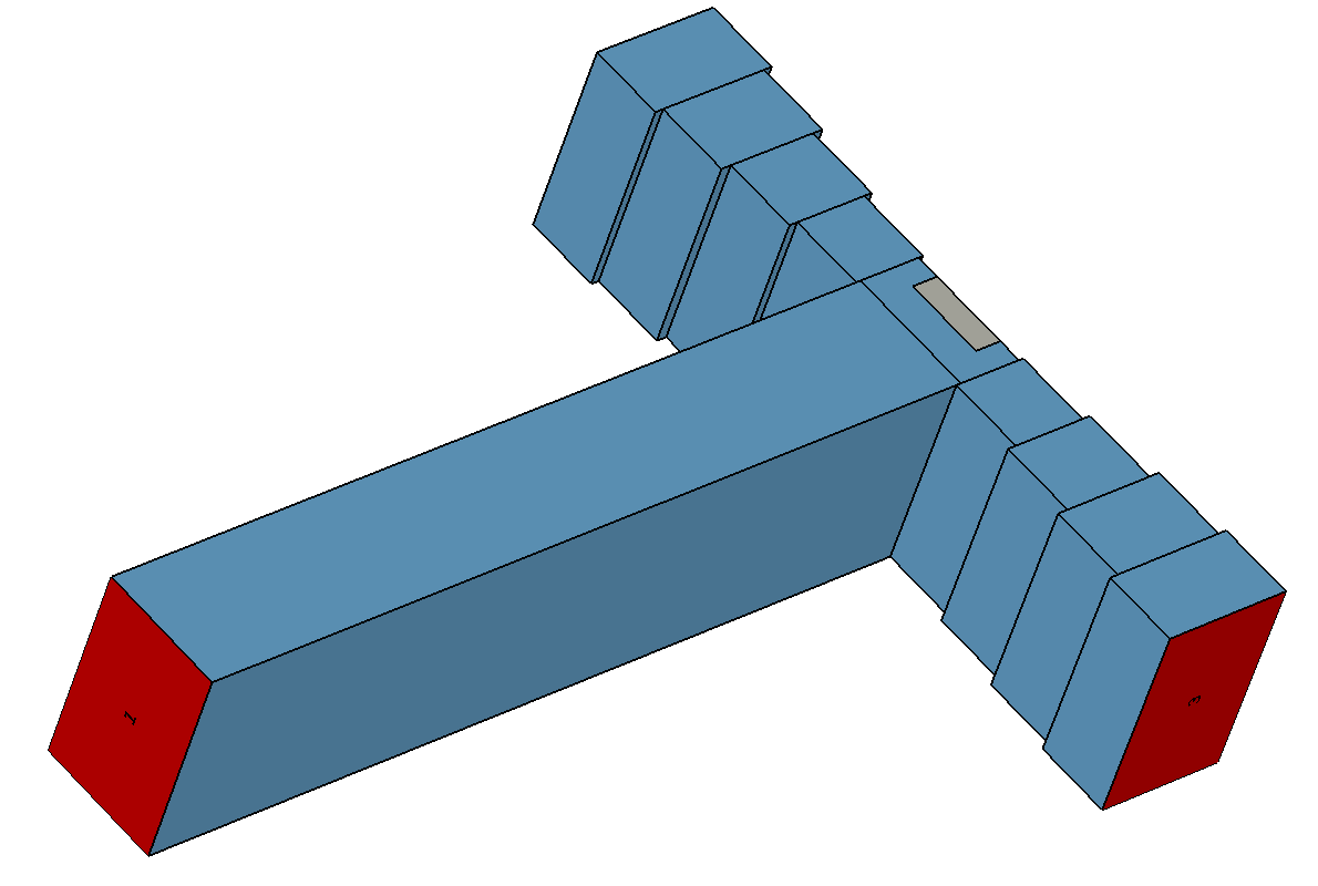
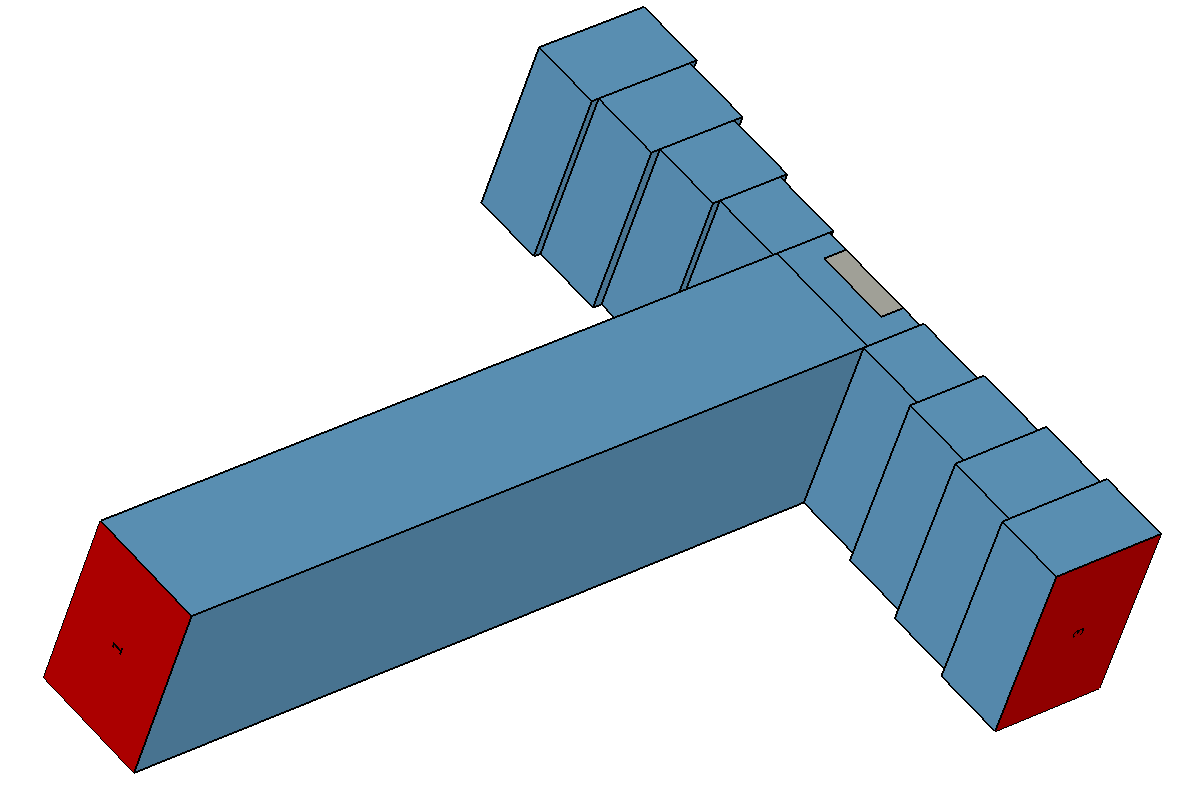
- Design: 14.5 mm x 9.525 mm 11-15 GHz Wideband Waveguide Power Divider
- Material: PEC and air
- File:
Waveguide/Splitter/WaveguidePowerDivider_11-15G.cst
- Figure:
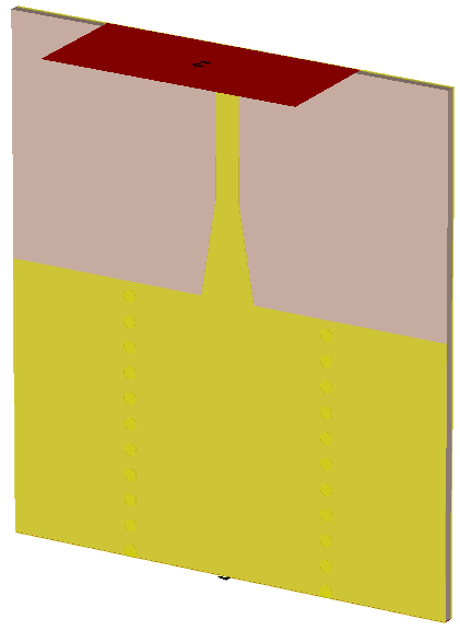
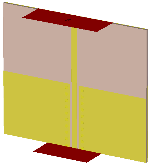
- Design: CPW to Microstrip
- Material: 0.01" Rogers RO3003
- File:
Transition/Rogers RO3003/CPW2MLIN_RO3003_KBand.cst
- Figure:
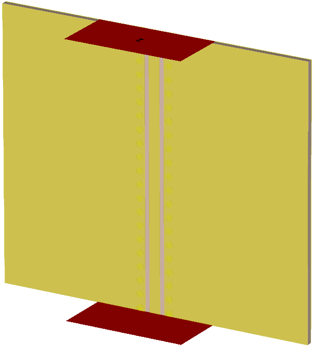
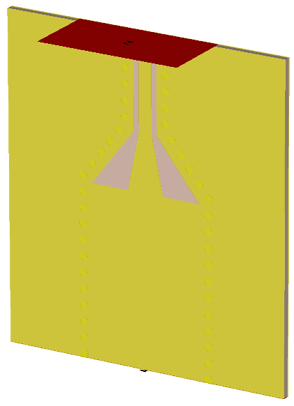
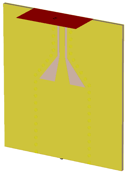
- Design: CPW to SIW
- Material: 0.01" Rogers RO3003
- File:
Transition/Rogers RO3003/CPW2SIW_RO3003_KBand.cst
- Figure:
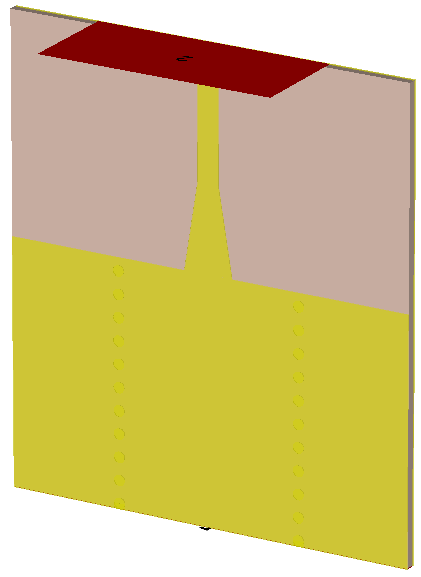
- Design: Microstrip to SIW on
- Material: 0.01" Rogers RO4350B
- File:
Transition/Rogers RO4350B/MLIN2SIW_RO4350B_KBand.cst
- Figure:
