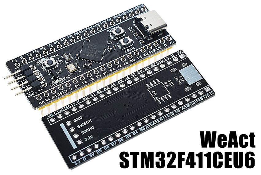
MicroPython board definition files for the WeAct V1.3 STM32F411CEU6 dev board.
Clone the board definitions to your MicroPython ports/stm32/boards folder.
cd micropython/ports/stm32/boards
git clone https://github.com/mcauser/WEACT_F411CEU6.git

cd ..
make BOARD=WEACT_F411CEU6This board can be flashed using DFU. To put the board in DFU mode, disconnect
USB, connect A9 to A10 and reconnect USB. Press and hold BOOT0. Press
and release RESET. Wait 0.5 seconds. Release BOOT0.
List attached DFU capable devices to check you are in DFU mode.
dfu-util -l

Found DFU: [0483:df11] ver=2200, devnum=12, cfg=1, intf=0, path="20-2", alt=3, name="@Device Feature/0xFFFF0000/01*004 e", serial="328A37623437"
Found DFU: [0483:df11] ver=2200, devnum=12, cfg=1, intf=0, path="20-2", alt=2, name="@OTP Memory /0x1FFF7800/01*512 e,01*016 e", serial="328A37623437"
Found DFU: [0483:df11] ver=2200, devnum=12, cfg=1, intf=0, path="20-2", alt=1, name="@Option Bytes  /0x1FFFC000/01*016 e", serial="328A37623437"
Found DFU: [0483:df11] ver=2200, devnum=12, cfg=1, intf=0, path="20-2", alt=0, name="@Internal Flash  /0x08000000/04*016Kg,01*064Kg,03*128Kg", serial="328A37623437"
Now you can flash the board using USB with the command:
make BOARD=WEACT_F411CEU6 deployOnce the upload is complete, disconnect USB, remove jumper between A9
and A10, then reconnect USB.
Alternatively, you can use the MicroPython command pyb.bootloader()
to get into DFU mode without needing to use the switch.
Currently, you need to unplug and replug the board in order to switch from DFU mode back to regular mode.
Once built and deployed, you can access the MicroPython REPL (the Python prompt) via USB serial.
screen /dev/tty.usbmodem1422 115200
# or
screen /dev/ttyACM0 115200In mpconfigboard.h you can configure the board to use F411CE internal flash or
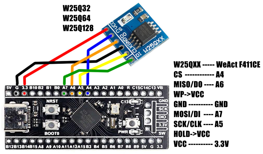
if you add a SPI flash chip to the bottom of the board you can use it instead.
If you use internal, there's only around 45kb free. With external you can have 4-16 MB.
// Use internal flash (512 KByte):
#define MICROPY_HW_ENABLE_INTERNAL_FLASH_STORAGE (1)

// Or use external SPI flash:
#define MICROPY_HW_ENABLE_INTERNAL_FLASH_STORAGE (0)
Tested with:
- Winbond W25Q32 (4 MByte)
- Winbond W25Q64 (8 MByte)
- Winbond W25Q128 (16 MByte)
Define the size that matches your flash chip.
// Winbond W25Q32 (4 MByte)
#define MICROPY_HW_SPIFLASH_SIZE_BITS (32 * 1024 * 1024)

// Or Winbond W25Q64 (8 MByte)
#define MICROPY_HW_SPIFLASH_SIZE_BITS (64 * 1024 * 1024)

// Or Winbond W25Q128 (16 MByte)
#define MICROPY_HW_SPIFLASH_SIZE_BITS (128 * 1024 * 1024)
If you use the wrong one, say 8 MB but you only have a 4 MB chip, it will appear as an 8 MB volume and let you write more than 4 MB, but you absolutely will get data corruption.
You can also use external SPI flash modules. Most modules have WP/IO2 and HOLD/RESET/IO3 pulled high, so you can't use Quad SPI mode, only SPI.
- STM32F411CEU6 ARM Cortex M4
- 100MHz, 125 DMIPS / 1.25 DMIPS / MHz
- 1.7V - 3.6V operating voltage
- 25MHz system crystal
- 32.768KHz RTC crystal
- 2.54mm pitch pins
- JTAG/SWD header
- 512 KByte Flash, 128 KByte SRAM
- 5x SPI, 3x USART, 5x I2S, 3x I2C
- 1x SDIO
- 1x USB 2.0 FS
- (Unpopulated) Winbond W25Q32 32Mbit SPI Flash
- 1x ADC (12-bit / 16-channel)
- 6x general timers, 2x advanced timers
- USB-C for power and comms
- Red power LED
- Blue user LED (PC13) active low
- 1x button for bootloader selection
- Reset button, 1x user buttons KEY (PA0)
- 2x20 side pins + 1x4 ISP pins
- no mounting holes
- Dimensions: 52.81mm x 20.78mm
- PA0-PA12, PA15
- PB0-PB10, PB12-PB15
- PC13-C15
- 1 PA4 CS
- 2 PA6 MISO
- 3 3V3 WP
- 4 GND GND
- 5 PA7 MOSI
- 6 PA5 SCK
- 7 3V3 HOLD
- 8 3V3 VCC
- 1 GND GND
- 2 PA14 SWCLK
- 3 PA13 SWDIO
- 4 3V3 VCC
- 1 GND
- 2 VBUS 5V
- 3 PA11 USB_DN
- 4 PA12 USB_DP
- PC13 Blue LED
- STM32F411CE on st.com
- Buy on AliExpress or search for "STM32F411CEU6"
- Buy on Taobao
- STM32F411 datasheet
- STM32F411 reference manual
- STM32F411CEU6 schematics
- STM32F411CEU6 PCB
- MCUDev Black STM32F407VET6
- MCUDev Black STM32F407ZET6
- MCUDev Black STM32F407ZGT6
- MCUDev DevEBox STM32F407VET6
- MCUDev DevEBox STM32F407VGT6
- WeAct STM32F411CEU6 - this board
- VCC GND STM32F407VET6 Mini
- VCC GND STM32F407ZGT6 Mini
Licensed under the MIT License.

