This is a demo project showing the integration of Sensirion's environmental sensors with Cypress devices supporting MBED OS, using http://thingsboard.io as an online dashboard. Sensors used are the SHTC1 temperature humidity sensor and SGP30 air quality sensor as well as the SPS30 particulate matter sensor.
This demo was prepared using the PSoC® 6 WiFi-BT Pioneer Kit (CY8CKIT-062-WiFi-BT), but should work on any MBED OS device, requiring only adjustments if a board has a non-standard setup.
This tutorial assumes that the user is familiar with MBED OS, MBED Studio, and Thingsboard. For questions on how to use these tools, please check their respective documentation.
If you have used the earlier demo made for Cypress' WICED SDK, you can skip right to Device setup.


The drivers for this demo are implemented using Sensirion's standard embedded drivers:
- SPS30: https://github.com/Sensirion/embedded-sps
- SHTC1: https://github.com/Sensirion/embedded-sht
- SGP30: https://github.com/Sensirion/embedded-sgp
This documentation is separate into the following chapters:
The hardware setup consists of the following components:
- PSoC® 6 WiFi-BT Pioneer Kit (CY8CKIT-062-WiFi-BT) or other compatible MBED OS reference design
- Sensirion Environmental Sensor Shield (ESS) featuring the SHTC1 and SGP30 sensors
- Sensirion SPS30 particulate matter sensor
The ESS requires a hardware platform which has Arduino-compatible expansion headers. Subsequenty, we will assume that the platform chosen has such expansion headers.
Note: Of course, the software will also work for other sensor boards featuring the SHTC1 and SGP30 sensor components, as long as they are correctly wired.
The interface of the SPS30 is described in its datasheet (chapter "Hardware Interface Specifications"). The connector is a ZHR-5 from JST Sales America Inc. The pin out is defined as follows when using the sensor in I2C mode:
| Pin | Function |
|---|---|
| 1 | VDD |
| 2 | SDA |
| 3 | SCL |
| 4 | SEL (GND for I2C) |
| 5 | GND |
To make the cable, it's easier to buy pre-crimped cables.
In addition, to connect to the reference design, you can use any jumper cables you have available. Choose either a male of female connector based on your reference design. To connect to the ESS, female connectors are required. If you don't have cables available, the following is an example of cables that would work:
Finally, to assemble the cable, procede as follows:
- Connect the five pre-crimped wires to the connector; ensure the cables are properly aligned
- Connect Wire 4
SELand 5GNDtogether
It is recommended to have at least 20cm or 8" of cable, which will allow for enough freedom to move the SPS30 around, so make sure you cut the jumper wires accordingly.
Note: It is also possible to use 2" pre-crimped wires, with longer jumper wires.

- Cut off a short piece of the jumper wires with the connector you need, strip a few mm of the other end of the cable
- solder the jumper wires to the pre-crimped wires wires; for Wire 4 and 5, connect only one connector

- Use heat shrink wrap and a heat gun to protect the solder joints
The pictures in this documention use a red jumper wire for VCC, green for SDA, yellow for SCL, and black for GND. You can choose any colors you like, of course. The resulting cable should look like this:

The ESS has a connector on the back with power supply lines (VCC, GND) as well as I2C lines (SCL, SDA). This allows to connect another sensor easily. In this case however, the SPS30 requires an exact 5V supply voltage (+/-10%), which the VCC pin on the back won't deliver. So in order to supply this, you can connect the VCC pin of the SPS30 cable to any available 5V pin on your hardware platform.
Alternatively, you can solder a jumper wire to the 5V pin of your ESS board, and use super glue to fix it to the back of the ESS board. This allows to keep the connectings hidden and the setup neat:
Front:

Back:

This demo is using http://thingsboard.io for visualization. To setup this demo, follow the following steps:
- first create an account on their demo server https://demo.thingsboard.io/login
- Go to the
Devicestab - create a new device; you can choose any name, but we're going to use
MBEDOS_INPUTin this documentation; make sure you replace any occurances of this with the device name you chose

- Go to the
Dashboardstab - import the dashboard from the downloaded ZIP, located in dashboard/air_quality_demo.json by pressing the red "+" button (bottom right), then the red "up arrow" button

- Open the newly created dashboard (It's going to be called "Air Quality Demo"
- Press the edit button (red pen, bottom right)
- Select the entity aliases button, and make sure you have an alias named
ess-input, Filter TypeSingle Device, TypeDevice, DeviceMBEDOS_INPUT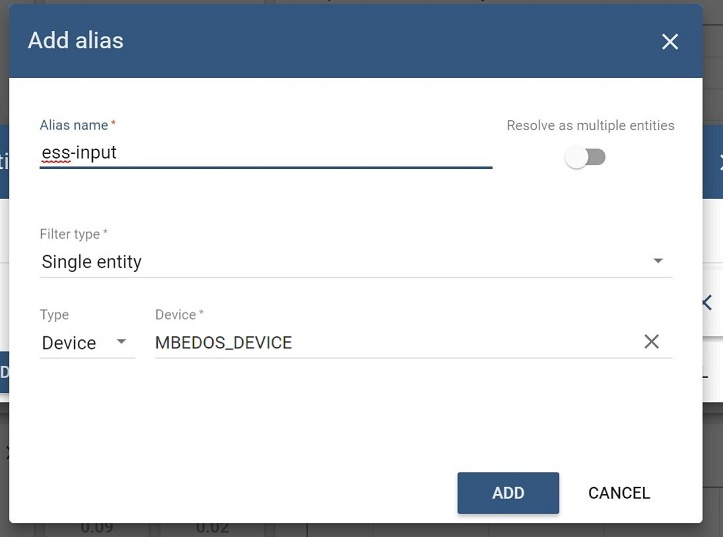

Your dashboard is now ready to be used!
If you want to share the dashboard with others, make sure both the device and dashboard are public:
- Go to the
Devicestab - Make the device public by pressing the "share" icon (see screenshot below)
- Go back to the
Dashboardstab - Make the Dashboard public by pressing the "share" icon, and store the URL you're getting from this dialog
![]()
For this demo, we assume that you have a working setup for MBED OS and MBED Studio for the PSoC® 6 WiFi-BT Pioneer Kit (CY8CKIT-062-WiFi-BT).
If you haven't configured MBED OS yet, please follow this tutorial to get up and running.
- Open MBED Studio
- Select "Import Program"
- Paste the URL of this repository (
https://github.com/winkj/air-quality-demo-mbed)
- Open the file
mbed_app.json - Change
wifi-ssid,wifi-passwordandwifi-securityto match your WiFi network - Change
thingsboard-tokento match the token from https://demo.thingsboard.io/devices (click on the device you created before, and select "Copy Access Token")
- Connect your platform to your computer, and compile and flash the firmware via the "Compile the platform and run" button ("play" icon)
- After flashing the image, the platform should reboot, and you should see the following output in the terminal window:
-----
T:     24.48
RH:    41.96
TVOC:  33
CO2eq: 400
PM2.5: 1.51
-----
If you see this output, the setup worked as expected. You can then enable the networking (see next step). Please note that the measured values - the numbers shown above - are a representation of the live environment, so they will most likely be different in your setup.
- To test with the networking enabled, open main.cpp and uncomment the
#define ENABLE_DATA_UPLOADline - Compile and flash the firmware via the "Compile the platform and run" button ("play" icon)
- Then, go to https://demo.thingsboard.io/devices, click on the device you created before, and click the "LATEST TELEMETRY"
- You should see a steady stream of data coming in
- Go to the dashboards tab, and select your new data.
- If everything works as expected, you should see the gauges and charts animated with the most recent data
The resulting dashboard should look like this: