NOTE 1: please fork this repo if using for your own use. I don't intend for this to be a central resource for airtag RE, more just some useful references for you to build on.
NOTE 2: This repo will not have any firmware or similar. Issues are disabled because the repo does not have any issues, it's perfect.
| Name | Description |
|---|---|
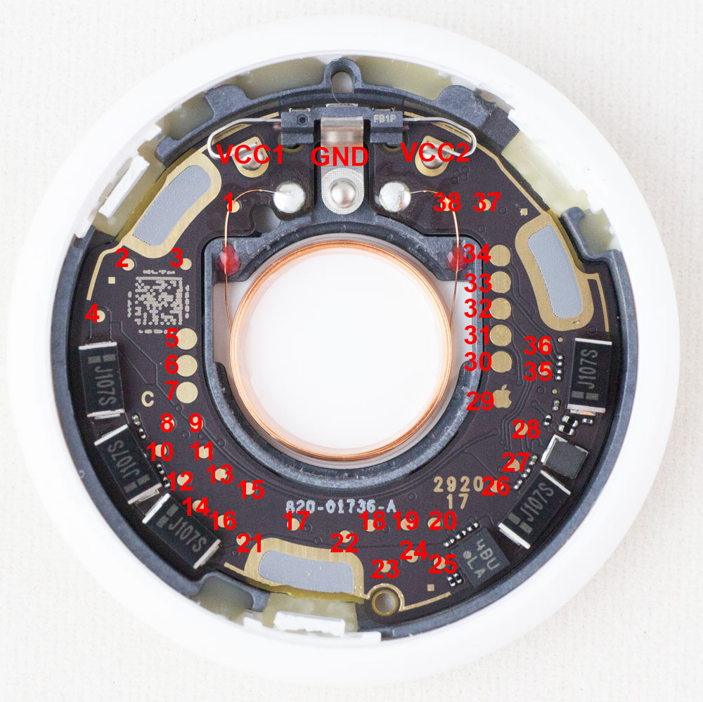
| VCC1 | +3.0V input (1 of 2 - both needed)* |
| VCC2 | +3.0V input (2 of 2 - both needed)* |
| GND | Ground |
| 5 | VCC2 (Connects to VCC2 input) |
| 6 | VCC1 (Connects to VCC1 input) |
| 7 | GND |
| 8 | nRF ball E2 (P0.16) |
| 9 | nRF ball D3 (P0.26) |
| 19 | 1.8V SPI Flash - Data In (COPI) / nRF ball H3 (P0.16) |
| 20 | 1.8V SPI Flash - Data Out (CIPO) /nRF ball H4 (P0.15) |
| 21 | 1.8V SPI Flash VCC |
| 22 | 1.8V SPI Flash - SCLK / nRF ball G3 (P0.17) |
| 24 | 1.8V SPI Flash - Chip Select (CS)/ nRF ball F4 (P0.11) |
| 29 | Apple Logo :) GND |
| 30 | nRF ball H1 (P0.21/nRST) |
| 31 | nRF ball H2 (P0.18/SWO) |
| 34 | 1.8V from nRF |
| 35 | nRF ball F1 (SWCLK) |
| 36 | nRF ball G1 (SWDIO) |
*NOTE: The big pads under the VCC1/VCC2 battery terminals are NOT connected. So if you remove the battery terminals you need to solder to the smaller pads where the terminals connected! I just apply 3.3V here, it's assumed the device will be designed to work with some variation.
The SPI connections (SCK/DI/DO/CS) are as above. If talking to the SPI flash chip note the following:
- You need to apply 1.8V on test point 21 to force the flash on.
- The nRF occasionally talks to SPI flash (especially when stuff like adding a device happens) which will interrupt this. But most of time the flash is powered off and thus the pins are tri-stated.
The nrf controls power to the SPI flash, so you need to override it by supplying 1.8V on test point 21.
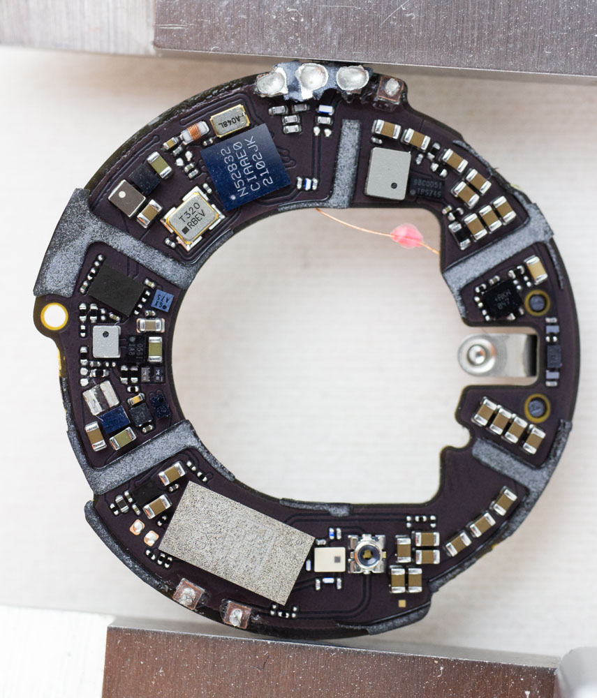
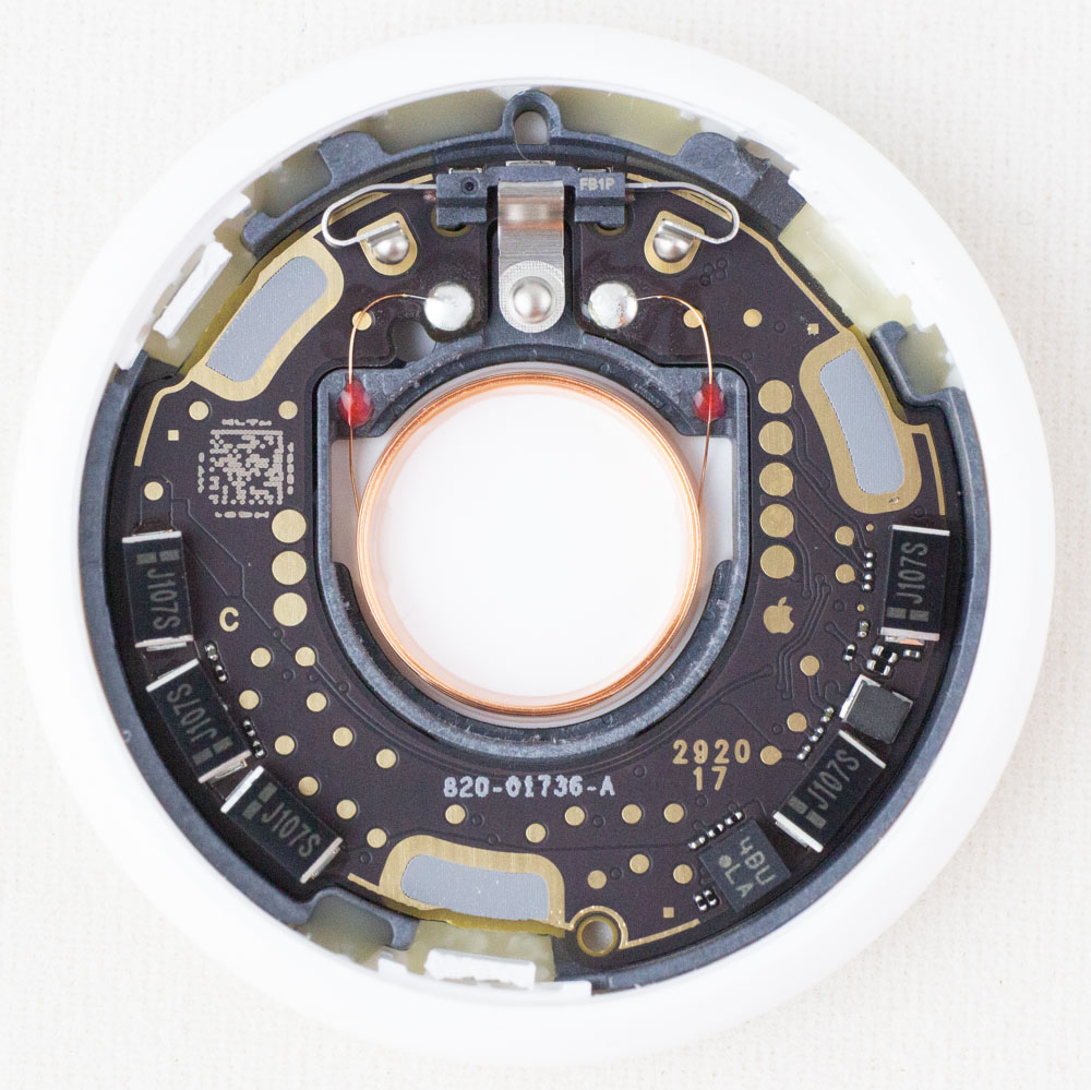
See repo for higher resolution.
This repo is licensed CC-BY-4.0 (to say explicitly - photos can be used commercially and only require attribution to Colin O'Flynn, no additional permission request is needed).


