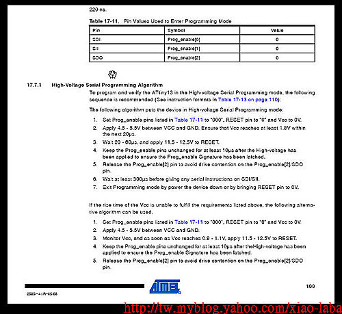
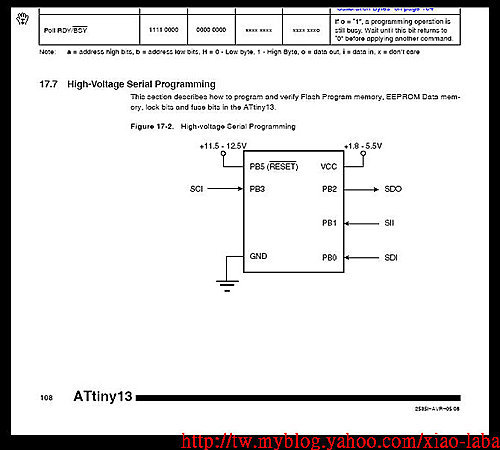
Attiny13, reset fuse and the chip, uses High Voltage (HV) Serial programming mode
Uses 5V-12V booster circuit to provide 12V+/-0.5V VPP to enter HV mode. no 12V supply available around
revised firmware, enable reset swtich working alone to reset fuse, LED blinking fast at the end to singal job done.
2020-JUN-08 update, 5v -> 12Vpp boost design
.
circuit testing, fine tune, test
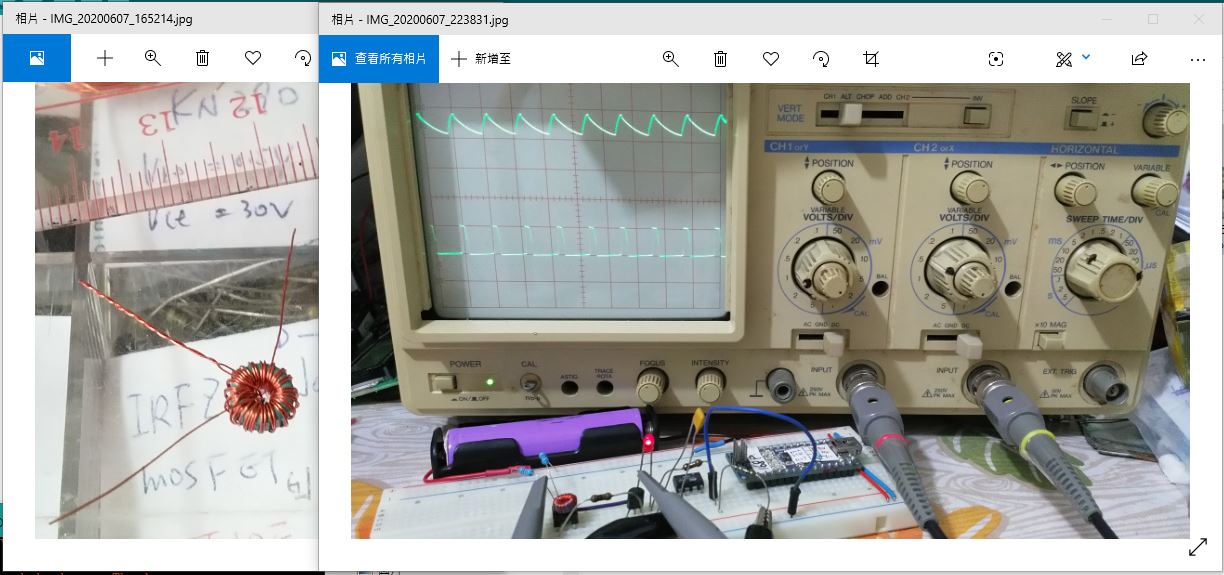
.
chip reset, terminal display
.
.
circuit design,
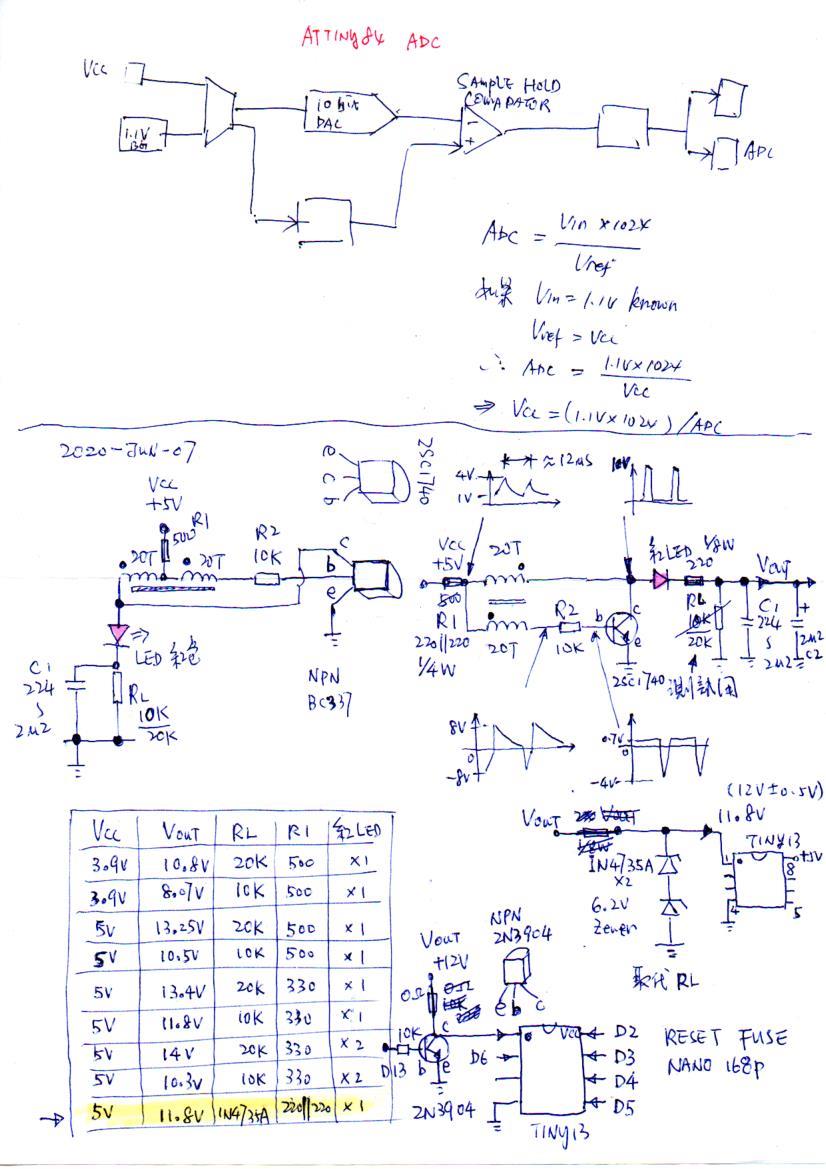
.
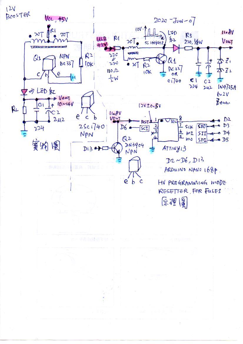
.
procedure

進入 高壓 PROGRAMMER 燒寫的方法

1) SDI, SII, SDO, RESET, VCC 接地
2) VCC 接到 4.5V - 5.5V, 保證 VCC 在20us 內超過 1.8V
3) 等待 20 - 60us, 然後 RESET 接 12V +/-0.5V) (最少 100ns)
4) 維持以上狀態最少 10us (此時應該已經進入了高壓模式)
5) 斷開 SDO 的接地, 避免搶奪, 短路
6) 等待最少 300us, 然後才操作 SDI 和 SII 對 ATTINY13 讀寫
7) 斷電離開或 RESET 接地便可脫離高壓模式
.
.
.
code

    pinMode(SDO, OUTPUT);     // Set SDO to output
    digitalWrite(SDI, LOW);
    digitalWrite(SII, LOW);
    digitalWrite(SDO, LOW);
    digitalWrite(RST, HIGH);  // 12v Off
    digitalWrite(VCC, HIGH);  // Vcc On
    delayMicroseconds(60);    // wait 20-60us
    digitalWrite(RST, LOW);   // 12v On
    delayMicroseconds(10);    // keep the state for at least 10us
                              // should be entered HV Programming mode
    pinMode(SDO, INPUT);      // Set SDO to input, relase
    delayMicroseconds(300);   // wait for 300us before giving instruction to SDI/SII
. . .
.
.
soruce code
.
hex, 115200baud, Atmega168p
.
hex, 115200baud, Atmega168p, with Arduino bootloader
.
.
.
.
2018-MAR-07
Attiny13, reset fuse and the chip, uses High Voltage Serial programming mode
