A Raspberry Pi Pico-based solution for capturing and converting the LCD output from Watara Supervision handheld consoles.
Watch the video:
This project allows you to:
- Replace the original LCD screen with a modern IPS display
- Convert your Watara Supervision from a handheld device to a TV console
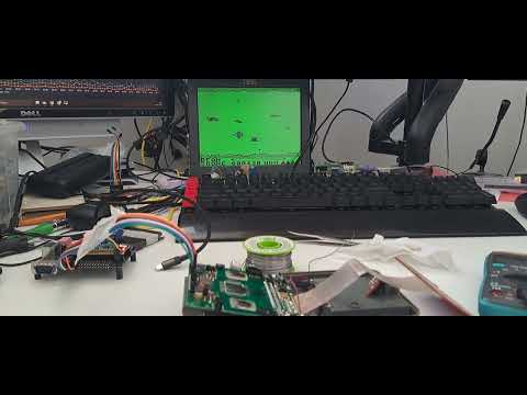
- Capture and process the raw LCD signals for display on external screens
The LCD grabber intercepts the digital signals from the Watara Supervision's video controller and converts them for use with modern displays.
- Raspberry Pi Pico
- Watara Supervision console
- Jumper wires for connecting to LCD pins
- Optional: IPS display for replacement
- Optional: Video output components for TV connection
| Pico GPIO | Watara Signal | Description |
|---|---|---|
| 16 | DATA0_PIN | LCD data line 0 |
| 17 | DATA1_PIN | LCD data line 1 |
| 18 | DATA2_PIN | LCD data line 2 |
| 19 | DATA3_PIN | LCD data line 3 |
| 20 | PIXEL_CLOCK_PIN | Clock signal for pixel data |
| 21 | FRAME_POLARITY_PIN | Frame sync/polarity indicator |
    1  2  3  4  5  6  7  8  9  10 11 12
    |  |  |  |  |  |  |  |  |  |  |  |
.---|--|--|--|--|--|--|--|--|--|--|--|---.
|   |  |  |  |  |  |  |  |  |  |  |  |   |
|   o  o  o  o  o  o  o  o  o  x  o  x   |
|            <LCD connector>             |
|                                        |
|              | | | | | |               |
|            -             -             |
|            -    C P U    -             |
|            -  (top side) -             |
|            -             -             |
|              | | | | | |               |
|                                        |
|      <controller board connection>     |
`----------------------------------------`
Supervision LCD pins:
- Ground
- Data 0
- Data 1
- Data 2
- Data 3
- Pixel clock
- Line latch
- Frame latch
- Frame polarity
- Unused (power control)
- +6V
- Unused (no idea what it does)
-
Clone this repository:
git clone https://github.com/xrip/watara-supervision-lcd cd watara-supervision-lcd -
Set up the Raspberry Pi Pico SDK according to the official documentation.
-
Build the project:
mkdir build cd build cmake .. make -
Flash the resulting
.uf2file to your Raspberry Pi Pico.
The code captures the Watara Supervision's LCD signals using the following approach:
- GPIO pins are configured to read the LCD data and control signals
- Core 1 handles the display/rendering functions
- The main core captures LCD data on rising clock edges
- Frame polarity changes indicate new frames
- Data is stored in the frame buffer (160x160 resolution)
- Display is handled with a 4-color palette matching the Watara's original greenscale
The system can refresh at full speed while maintaining accurate representation of the original display data.
The code supports multiple display modes through the graphics library:
- Default mode that matches the original display's appearance
- Optional color palette customizations
- Flash mode for special visual effects
You can modify the display appearance by adjusting:
- Color palette values in the
graphics_set_palette()calls - Buffer dimensions for different scaling options
- Timing parameters for different Watara Supervision models
To enable debugging, uncomment the #define DEBUG line to activate LED blinking on each new frame. This helps verify that frames are being captured correctly.
Contributions to improve the project are welcome! Please feel free to submit issues or pull requests.
[Your preferred license here]
- Project based on https://github.com/DutchMaker/Supervision-LCD
- Watara Supervision hardware documentation resources
- [Any other acknowledgments]