Zeta4 Drive & Arduino
Getting an Arduino UNO to talk to a Parker Zeta4 drive
Wiring the Drive
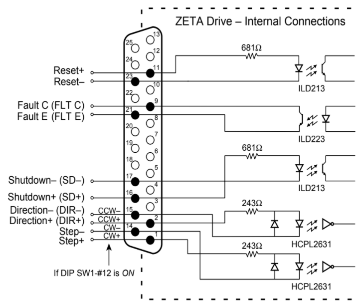
Wire the 25 Pin D Connector according to the following drawing:

Pin Descriptions
Step
Type: Input
Pins: STEP+ (pin 1) & STEP- (pin 14)
Step: Voltage Applied (step occurs on rising edge)
Step Pulse:
- 200 nanosecond minimum pulse width
- 200 nanosecond minimum off time
- 2 MHz maximum pulse rate
| Input Current (mA) | Input Voltage (VDC) | |
|---|---|---|
| Minimum | 6.5 mA | 3.5 V (min. required for on or high signal) |
| Maximum | 15 mA | 5.2 V |
Direction
Type: Input
Pins: DIR+ (pin 2) & DIR- (pin 15)
CCW: 0V or negative voltage between DIR+ & DIR-
CW: Positive voltage between DIR+ & DIR-
| Input Current (mA) | Input Voltage (VDC) | |
|---|---|---|
| Minimum | 6.5 mA | 3.5 V (min. required for on or high signal) |
| Maximum | 15 mA | 5.2 V |
Clockwise & Counterclockwise
Type: Input
Pins: CCW+ & CW-
| Pin # | SW1-#12 OFF | SW1-#12 ON |
|---|---|---|
| 1 | STEP+ | CW+ (pin 1) |
| 14 | STEP- | CW- (pin 14) |
| 2 | DIR+ | CCW+ (pin 2) |
| 15 | DIR- | CCW- (pin 15) |
Shutdown
Type: Input
Pins: SD+ (pin 16) & SD- (pin 17)
Shutdown: Voltage Applied
Normal Operation: Voltage Removed
| Input Current (mA) | Input Voltage (VDC) | |
|---|---|---|
| Minimum | 2.5 mA | 3.5 V (min. required for on or high signal) |
| Maximum | 30 mA | 13 V |
| Maximum Reverse | 5 V |
Reset
Type: Input
Pins: RESET+ (pin 11) & RESET- (pin 23)
Reset: Voltage Applied
Normal Operation: Voltage Removed
Reset Voltage Pulse: 250 nanosecond minimum pulse width
| Input Current (mA) | Input Voltage (VDC) | |
|---|---|---|
| Minimum | 2.5 mA | 3.5 V (min. required for on or high signal) |
| Maximum | 30 mA | 13 V |
| Maximum Reverse | 5 V |
Fault Output
Type: Output
Pins: FLT C (pin 9) & FLT E (pin 21)
VCE: 30 VDC
VCESAT: 1 VDC
Collector Current: 40 mA minimum
Dissipation: 40 mW maximum
Links
Zeta4 Drive Installation Guide
Zeta4 Drive Dimensional Drawings
Zeta4 Drive DXF