This is multiple USB UART Bridge with Raspberry Pi Pico. I know there are some similar implementations, but this has useful additional functions for dev environment.
- 6 USB-UART Bridges
- 2 Pico Hardware UARTs
- 4 PIO Based UARTs provided by Arduino Pico/RP2040 board package
- Pico USB Console other than the Bridges is also available for some functions
- Capturing USB-UART Bridged data
- counts Tx/Rx Bytes of each USB-UART Bridge
Before

After

You can use complied UF2 file in convenient.
If you will build UF2 yourself see #4.Build Requirement
This is troublesome work but needed. You can find 7 new USB COM ports on Device Manager.
-
Find COM ports witch 'Device Instance Path' of property is
USB¥VID_2E8A&PID_000A&MI_00¥... -
Note the linked COM port numbers
USB¥VID_2E8A&PID_000A&MI_00¥...
MI_00 = Pico USB console
MI_02 = USB-UART Bridge 0
MI_04 = USB-UART Bridge 1
MI_06 = USB-UART Bridge 2
MI_08 = USB-UART Bridge 3
MI_0a = USB-UART Bridge 4
MI_0c = USB-UART Bridge 5
I changed COM port FriendlyName in the Registry at my own risk to escape from pain.

| Bridge | GPIO Pin (Tx/Rx) |
|---|---|
| USB-UART Bridge 0 | 0/1 |
| USB-UART Bridge 1 | 4/5 |
| USB-UART Bridge 2 | 8/9 |
| USB-UART Bridge 3 | 12/13 |
| USB-UART Bridge 4 | 16/17 |
| USB-UART Bridge 5 | 20/21 |
The environment
graph LR;
    1(PC)<-.->|COM9/Bridge0 USB|2(USB-UART-Bridge/Pico);
    1<-.->|COM7/Pico console|2;
    2<-.->|Bridge0 UART|3(DeviceA);
Type 'help' at COM7 terminal. This is vscode SERIAL MONITOR example.
---- Sent message: "help\n" ----
Usage:
  show              : show current parameters
  cap num           : enable capture for bridge<n>
  uncap num         : disable capture for bridge<num>
  capmode num mode  : set capture mode for bridge<num> to <mode>
                    : mode: 1=TXT, 2=HEX, 3=TXT&HEX
  clear {num | all} : clear bytes count
  help              : print this help
Type 'cap 0', 'capmode 0 1' and 'show'
---- Sent message: "cap 0\n" ----
Capture:
  enable for B0 (GP0/1)
---- Sent message: "capmode 0 1\n" ----
Cpature mode:
  B0 (GP0/1) capture mode to 1
---- Sent message: "show\n" ----
Show:
  bridge        |  baudrt | capture | capmode | capdelim  |  usb->uart |  uart->usb
  B0 (GP0/1)    |  115200 | off     | TXT     | \n  ( 10) |        474 |      85463
  B1 (GP4/5)    |  115200 | off     |     HEX | \n  ( 10) |          0 |       8261
  B2 (GP8/9)    |  115200 | off     |     HEX | \n  ( 10) |          0 |          0
  B3 (GP12/13)  |  115200 | off     |     HEX | \n  ( 10) |          0 |          0
  B4 (GP16/17)  |  115200 | off     |     HEX | \n  ( 10) |          0 |          0
  B5 (GP20/21)  |  115200 | off     |     HEX | \n  ( 10) |          0 |          0
Run sample MicroPython Program at the DeviceA
import time
from machine import UART,Pin

u = UART(0, 115200)
i = 0
while True:
    u.write(str(i))
    i += 1
    u.write(' Hello World !\n')

    time.sleep(1)
Then the Bridge captures them at COM7
B0 (GP0/1) (uart->usb txt):0 Hello World !\n
B0 (GP0/1) (uart->usb txt):1 Hello World !\n
B0 (GP0/1) (uart->usb txt):2 Hello World !\n
...
COM9 terminal shows
0 hello World !
1 hello World !
2 hello World !
...
-
Required software
- Arduino IDE
- Arduino Pico/RP2040 board package
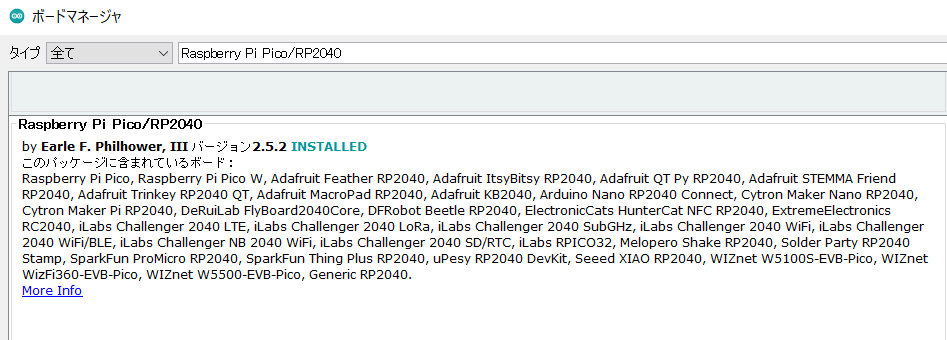
- current UF2 is built with Arduino IDE 1.8.19 and RP2040 package 2.5.2
-
Board Configuration
- Use Adafruit TinyUSB as USB stack in the board configuration menu
-
You have to change some package source code
- '#define CFG_TUD_CDC 1' to '#define CFG_TUD_CDC 7'
in the tusb_config_rt2040.h - 'uint8_t _desc_cfg_buffer[256];' to 'uint8_t _desc_cfg_buffer[1024];'
in the class Adafruit_USBD_Device in the Adafruit_USBD_Device.h
- '#define CFG_TUD_CDC 1' to '#define CFG_TUD_CDC 7'

- UART Baudrate is fixed 115200 bps. if you change it you have to change source code.
- Use LF or CRLF to send commands to Pico USB console.
- Capture function is for light debugging purpose. Capturing multiple bridges at the same time can overflows the buffer.
- Enable / Disable capture on each bridge.
- bi-directional data streams are captured simultaneously.
- Captured data is displayed in TEXT, HEX or TEXT&HEX.
- If you choose TEXT mode and data stream contains bytes which numbers is greater than 127, the text could be unreadable. Control characters less than 128 are translated readable strings.
- In HEX mode, the data column is divided into 16 byte units and displayed. data less than 16 bytes will be displayed 1 second after being received.
- In TEXT mode and TEXT&HEX mode, the data is divided by delimiter. If a text column exceeds buffer size, the text column is divided into buffer size units.
- You can specify the delimiter which is a character byte.
- There are three ways to specify.
- A number from 0 to 255.
- A special character \0 \b \t \n \v \f or \r.
- A character such as /.
- If you wanna specify SPACE character, use number 32.
- triggered capturing
- rewriting data stream
- UART-UART Bridging and capturing by USB
- and so on..