First, I want to thank the owners of the following two GitHub repositories, whose hard work I used as foundation and inspiration when I was reverse engineering the MHO-C401 sensor:
The current repository is a fork of https://github.com/GitJer/XiaomiMiaoMiaoCe due to my desire to use a C++ based approach, but the present README is heavily based on the reverse engineering efforts of https://github.com/jonathonlui/MHO-C201.
The Mijia MHO-C401 (also sold as Xiaomi MiaoMiaoCe MMC-C401) is a Bluetooth-enabled thermometer and hygrometer display with a segmented e-ink screen.
A multimeter in continuity mode was used to trace the connections between the stock MCU (TLSR8251) and the display controller (which is unknown - MHO-C201 seems to be using HT16E07, but its connections and commands differ from those used in MHO-C401).
To determine the purpose of each connection, a logic analyser was used to capture the signals (see ./captures) between the MCU and display controller. The captures were compared to a number of e-ink display controllers' datasheets, but a single and exact match was not found.
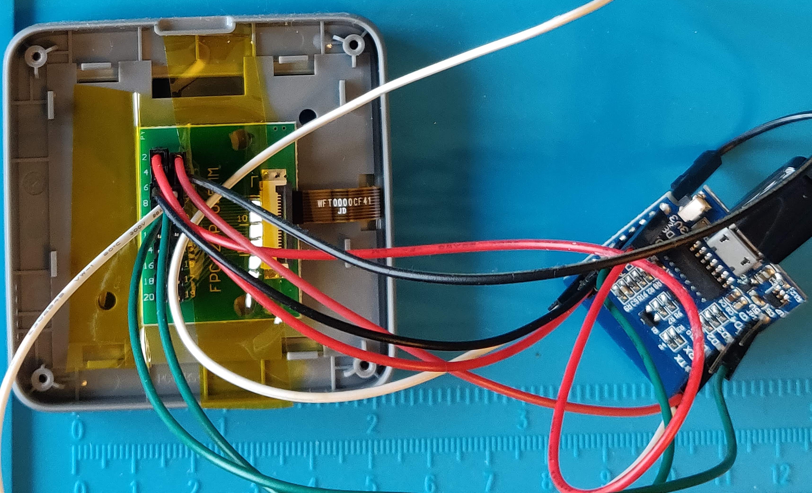
The display was disconnected from the MCU board and it was instead connected to a breakout board in order to be able to control it easily with a Wemos D1 mini EPS8266-based board:
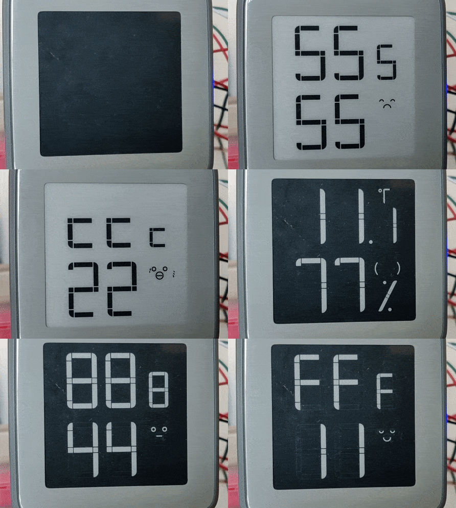
An Arduino-compatible C++ library with a few examples to control the display is in: ./XiaomiMiaoMiaoCeBT.
- Display controller IC is unknown, but unlike that used in MHO-C201, it is not HT1607. Some of the commands captured between the MCU and Display match HT16E07 datasheet, some match other display controllers
-
VDL - Driver low supply voltage – bypass to GND with 1μF capacitor
- Connected to capacitor at C3.
- Measured voltage: 6.5V.
-
VDH - Driver high supply voltage – bypass to GND with 1μF capacitor
- Connected to capacitor at C2.
- Measured voltage 12.6V
-
GND
-
VDD - Between 2.4 to 3.6V
-
SDA (data) - connected to pin 13 (SPI_DO) of MCU
-
SCL (clock) - connected to pin 1 (SPI_CK) of MCU
-
CSB (latch) - connected to pin 24 (SPI_CS) of MCU
- Low during data clock pulses, pulses high after 9 clocks pulses
-
UNKNOWN (probably SHD_N, connected to pin 17 (PC4) of MCU
- Maybe this is charge pump enable pin – low shutdown
-
RST_N - connected to pin 3 (SWS/PA6) of MCU
-
BUSY_N - connected to pin 2 (PA5) of MCU
- Busy flag output pin
- BUSY_N="0" – driver is busy, driver is refreshing the display
- BUSY_N="1" – driver is idle, host can send command/data to driver
- Busy flag output pin
MCU at U3: TLSR8251 datasheet
The MCU updates the display 3 times on startup:
- MCU powers on
- After 100 ms, sets Display SHD_N high
- Send low pulse on RST_N for 110 microseconds
- Update #1: Full black clear. This update turns on then off all black segments using special LUT values (see below for Update Display Sequence)
- BUSY_N is low for about 3400 ms between after sending DRF
- Send low pulse on RST_N for 110 microseconds
- Update #2: Full white clear. This update turns on then off all white segments using special LUT values (see below for Update Display Sequence)
- BUSY_N is low for about 1950 ms between after sending DRF
- Send low pulse on RST_N for 110 microseconds
- Update #3: Set all black segments on (except the background segment).
- BUSY_N is low for about 1950 ms between after sending DRF
- Wait 100ms
- During this 100ms the MCU reads temp from Sensor
- Update #4: Set some black/white segments on/off (to show temp / humidity)
- BUSY_N is low for about 1950 after DRF
- Sends final POWER_OFF command
After startup the MCU will periodically read the Sensor and sets on/off state of the segments.
-
Send low pulse on RST_N for 110 microseconds
-
Send: Power On (POWER_ON - 0x04)
-
Wait for BUSY_N high
-
Send: Panel Setting (PANEL_SETTING - 0x00)
-
Send: Power Setting (POWER_SETTING - 0x01)
-
Send: Power Off Sequence Setting (POWER_OFF_SEQUENCE_SETTING - 0x03)
-
Send: Frame Rate Control (FRAME_RATE_CONTROL - 0x30)
-
Send (ONLY when not initialising): PARTIAL_DISPLAY_REFRESH - 0x15
10.1. Send: LUTV (0x20), LUT_KK (0x23), LUT_KW (0x26)
- The LUT define the timing and voltages for turning on/off the segments
- There are 3 sets of LUT values
- LUT values to fully clear the display by turning on and then off all the segments
- LUT values to turn off segments
- LUT values to turn on segments
10.2. Send LUT (0x24) and LUT (0x25)
- Send two additional LUT tables when performing update (i.e. not during the initialisation phase)
- Send: Data Start Transmission 1 (DATA_START_TRANSMISSION_1 - 0x18)
- Logic analyzer captures show DATA_START_TRANSMISSION_1 command is 18 bytes.
- Send: Data Start Transmission 2 (DATA_START_TRANSMISSION_2 - 0x1C)
- Logic analyzer captures show DATA_START_TRANSMISSION_2 command is 18 bytes.
-
Send: Display Refresh (DISPLAY_REFRESH - 0x12)
-
BUSY_N goes low which means display is refreshing
-
Wait for BUSY_N high
-
Send: Power Off (POWER_OFF - 0x02)
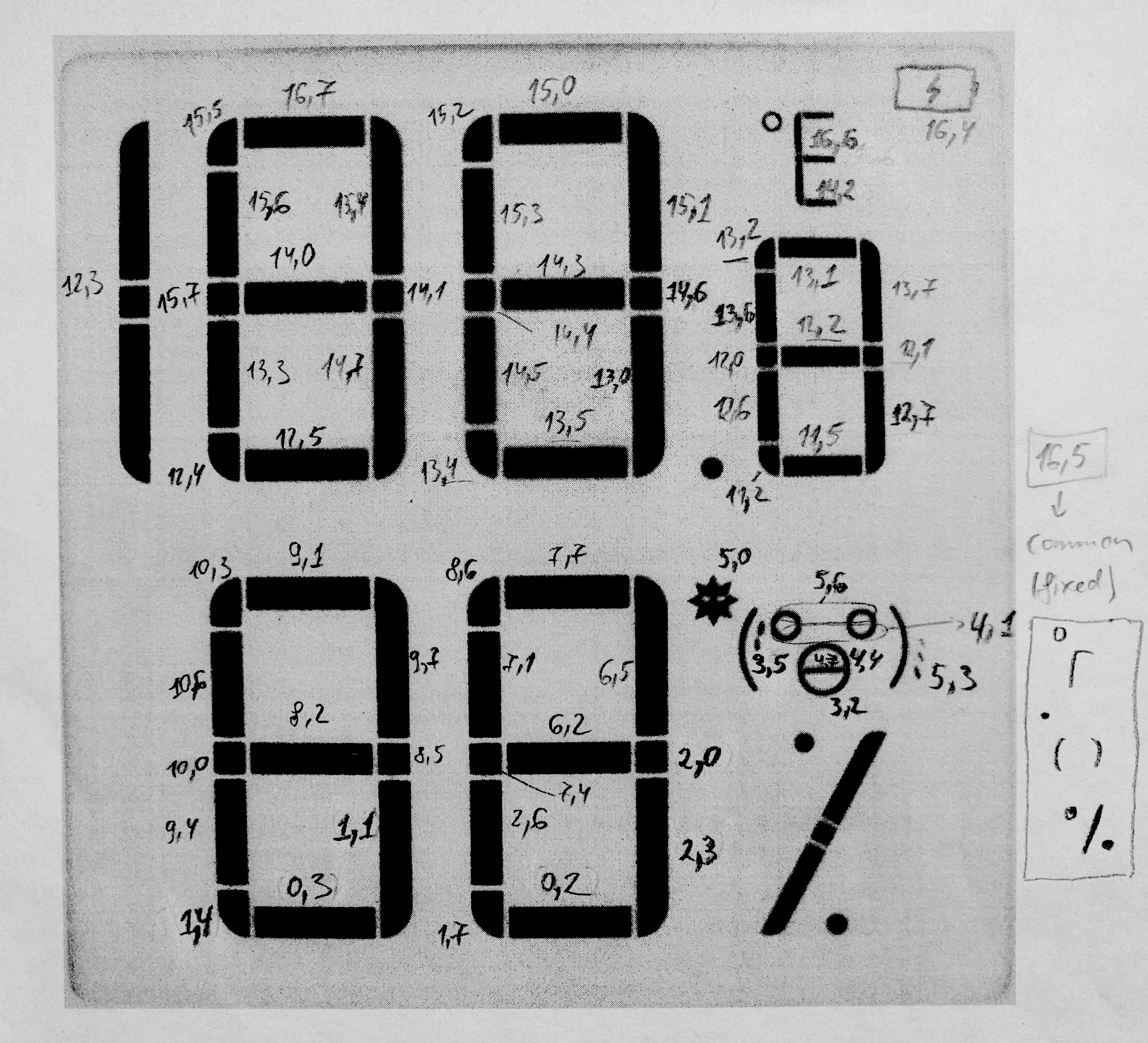
Segments are mapped accross the bits (0-7) of 18 bytes (0-17), sent with DATA_START_TRANSMISSION command. The exact mapping was determined by cycling through all the bits and bytes, using the sample here: find_segment_positions.
Following image shows how the segments are mapped: first number is the byte, second number is the bit within that byte:
This convention is used in the code when defining logic groups of segments, like: top_left, bottom_right, face etc.
Segment (16,5) turns on the parts of the display that are always on during normal usage:
- Degree symbol and common parts of C and F
- Decimal point
- Side of faces
- Percent sign
Segment (17,7) is the "background"
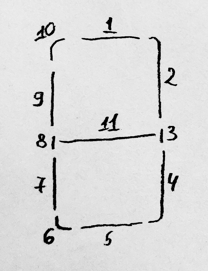
In order to facilitate the display of Hexadecimal numbers, another two-dimensional array is used - digits[16][11]. This array defines how each hexadecimal digit maps to the following group of segments (1 to 11):
You can check the following example, demonstrating how to "draw" numbers: numbers_and_shapes.


