A program for Arduino Uno that makes it possible to connect a TI-83 calculator to a computer
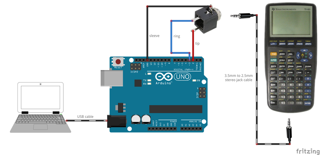
This program turns an Arduino Uno board into an adapter between a TI-83 graphing calculator and a computer. In order to use it upload serial2ti83.ino to an Arduino board using the standard Arduino IDE and connect the 2.5mm jack port on the bottom of TI-83 to Arduino according to the following table:
| Jack port | Arduino |
|---|---|
| sleeve | GND pin |
| tip | pin 2 |
| ring | pin 3 |
You can now run some linking program, e.g. TiLP and start exchanging data (upload programs, take screenshots, dump ROM, manage variables, etc.). In case of TiLP make sure to go to File->Change Device first and choose GrayLink cable and TI-83 calc.
Optional: before uploading serial2ti83.ino it is recommended to increase the size of hardware serial buffers to make the connection more reliable. Open HardwareSerial.h from you Arduino installation folder (usually C:\Program Files (x86)\Arduino\hardware\arduino\avr\cores\arduino) and change these 2 lines:
#define SERIAL_TX_BUFFER_SIZE 64
#define SERIAL_RX_BUFFER_SIZE 64
to:
#define SERIAL_TX_BUFFER_SIZE 256
#define SERIAL_RX_BUFFER_SIZE 256
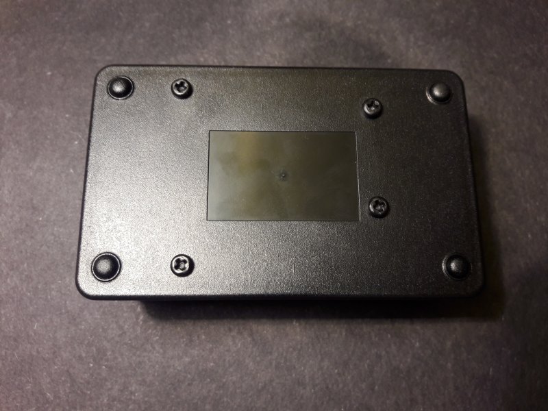
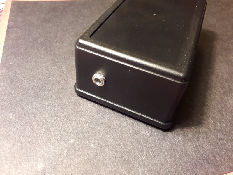
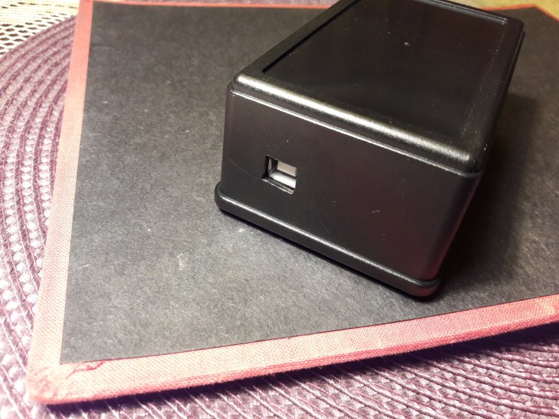
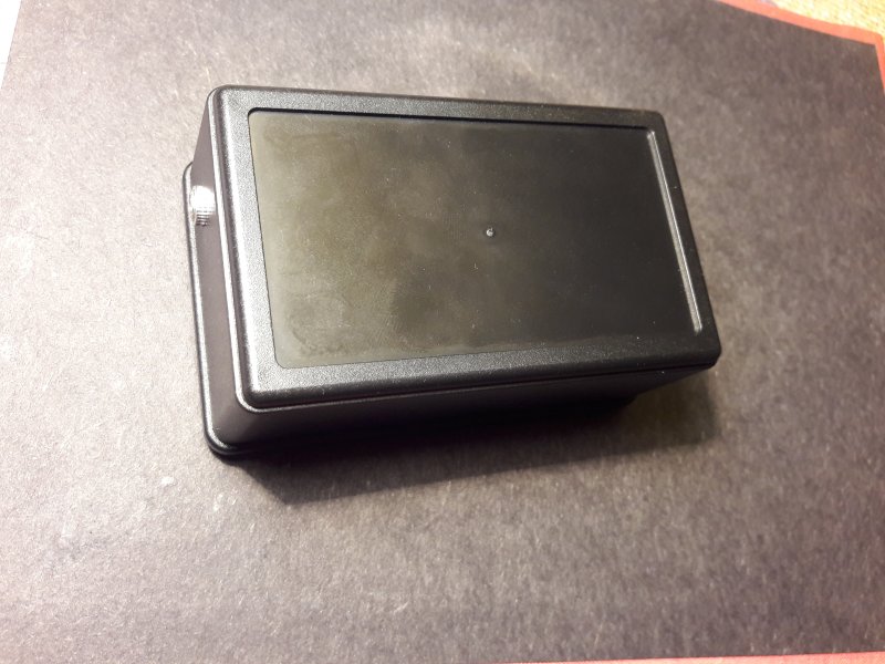
Here is an example of how you can put an Arduino board inside a box and attach a 3.5mm jack socket to the box to make a device that is convenient to use.
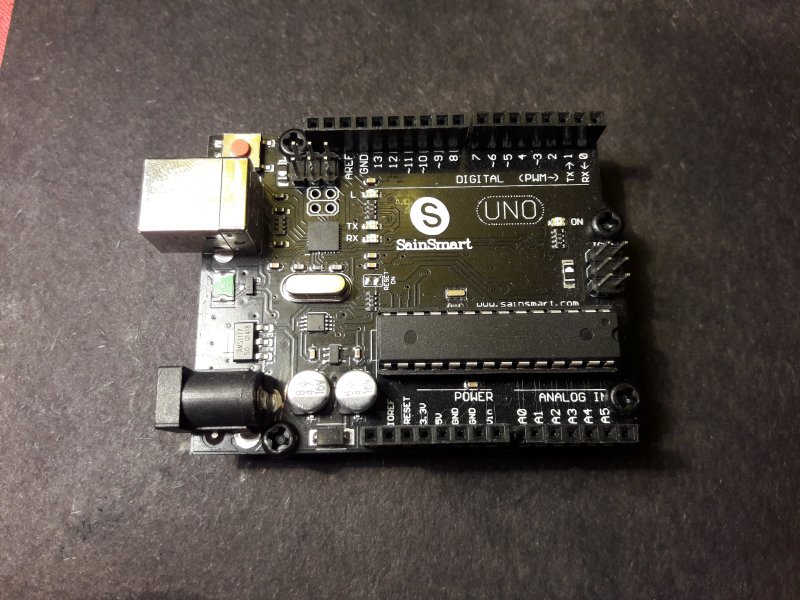
- Arduino Uno board (or clone)
- plastic project box (search for "ABS Plastic Electronic Enclosure Project Box Black 103x64x40mm" on Banggood, it's about $3.5)
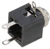
- 3.5mm panel mounted stereo jack socket (eBay, $0.99)
- nylon M3x10mm standoffs (eBay, $1.69 for 25 pieces)
- nylon M3x6mm philips screws (eBay, $1.79 for 25 pieces)
- 3.5mm to 2.5mm stereo jack cable (eBay, $0.99)
Note: not every 2.5mm jack plug fits TI-83 smoothly. You may need to file away bits of plug's plastic housing so it goes all the way into the socket
- some jumper cables
- basic tools (soldering iron, philips screwdriver, dremel tool, drill, files, etc.)
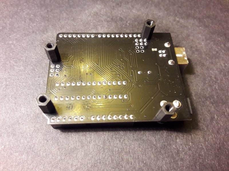
The first step is to attach standoffs to the Arduino board:
Sometimes you will need to file edges of the DC socket and connector headers to make space for screws.
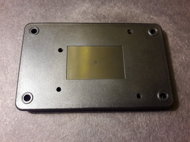
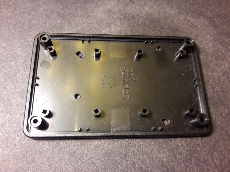
Drill 4 holes in the bottom part of the box. The holes should match Arduino's layout:
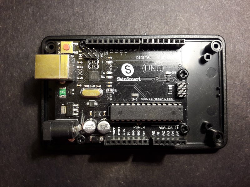
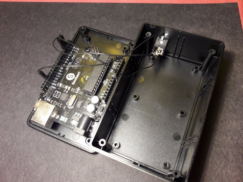
Screw the Arduino board to it:
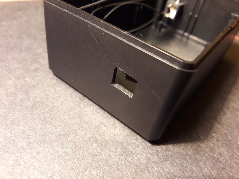
Make a rectangular opening for the USB plug in the top part of the box. You may use a drill and finish with a file. The opening should be correctly positioned so that it matches with the USB socket.
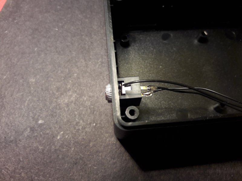
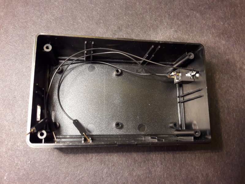
Drill a hole on the other side of the top part of the box and attach the 3.5mm jack socket. Solder 3 jumper cables to it.
Connect the jumper cables to the Arduino (see schematic above).
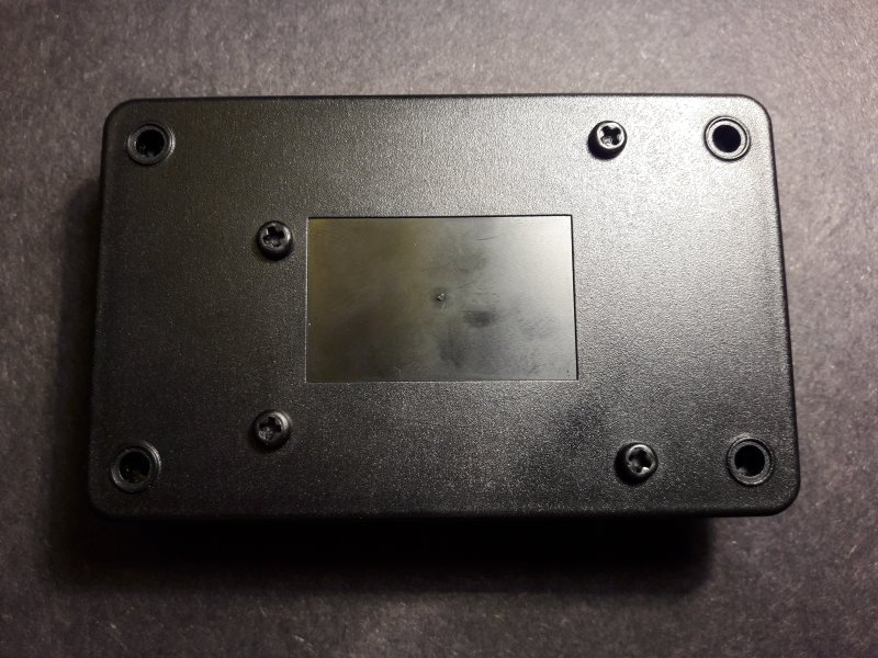
Assemble the box. Use the 4 screws included with it.
Insall 4 rubber feet:
This is the final result:
