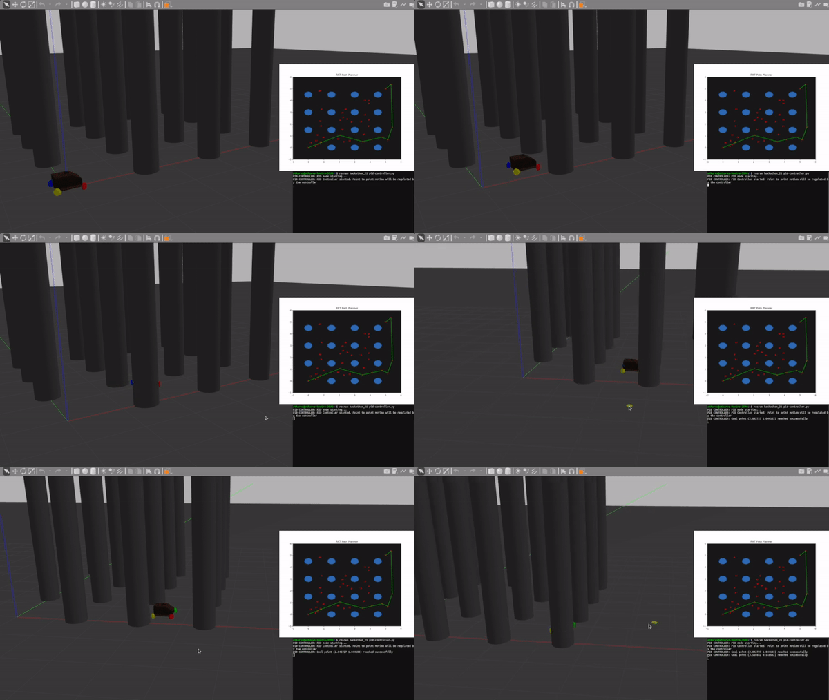
This repository contains the task for the ERC ROS Hackathon 2021.
Link to the hackathon repository
The hackathon task aims to introduce the participant to ROS and go through the process of building a small robotics software stack.
The problem statement requires the robot to autonomously plan a path through a field of known static obstacles and traverse to a given goal point.
ROS and gazebo have been used for the simulation. The code is written in Python using the rospy module to interface with ROS.
The robot used for the task is Omnibase, a simulator of a 4 wheel drive robot based on Trotbot developed by the Electronics and Robotics Club of BITS Goa.
The task briefly covers motion planning and a control system to regulate the motion of a robot using ROS, Gazebo and Python.
The repository contains the ROS package for the hackathon named 'hackathon_21'.
There are three scripts for three nodes namely:
-
obstacle-publisher.py: Publishes the locations of the static obstacles
-
path-planner.py: Subscribes to the obstacle publisher and takes user input for goal point, then plans a path for the robot to reach the goal. Publishes a list of points to traverse through from the initial position to the goal.
-
pid-controller.py: Subscribes to the path published by the planner and implements a PID controller to traverse point to point from the initial position to the goal
The package contains rosbag files of some test runs.
The file hackathon-trial-run.mkv contains a video of one of the test runs.
Path planning is one of the most important elements of an autonomous robot.
Many path planning algorithms have been developed and are useful in different scenarios, depending on the target and the constraints. (eg. Sampling based algorithms may be used over Grid based algorithms in case of a constraint on computational or processing power).
A popular sampling based algorithm is the RRT or Rapidly exploring Random Tree algorithm.
For the purpose of this project a modified version of RRT algorithm has been implemented.
In a tree structure, every node has only one parent
-
- Randomly sample a point in the given space and if it lies inside an obstacle, sample a point again till a point that is at a distance of clearanceRadius is obtained.
clearanceRadius = botRadius(approximate radius of the circle circumscribing the bot) + obstacleRadius
This ensures that if the bot is positioned on that point, it would not be in contact with an obstacle.- Connect this point to the nearest available 'Node' under the condition that the line joining the nodes is clear of any obstacle.
- Continue this process until a node from which a direct path to the goal point is feasible is found
- Once the goal node is found, trace back the path by tracking the parent of the goal node, and the parent of that node, and so on till the initial node (0, 0) is reached
- Store the points in a list and publish it on a rostopic ('path')
- Randomly sample a point in the given space and if it lies inside an obstacle, sample a point again till a point that is at a distance of clearanceRadius is obtained.
-
- The path generated is not always efficient. Many times a shorter and direct path is available. (Solution, RRT*)
- The algorithm is modified from fundamental RRT so that when a new node is sampled, it directly connects it to the nearest node if the path is feasible(does not cross an obstacle).
In case of RRT, the new node is generated at a distance which is the minimum of the direct distance between the two points or a pre defined 'step size' in the direction of the new sampled point.
This leads to most of the sampled points being used (rather than discarded because the path to it leads through an obstacle) and more area of the field is explored. - The step of connecting a sampled point directly to the goal point if feasible may accomplish the task in less time. But as a consequence, it leaves a large part of the map unexplored.
A control system is the backbone of any working system.
In this case, a controller is needed for the robot to traverse from one point to another.
A PID(Proportional Integral Derivative) controller is a very popular closed loop control feedback controller used in many systems.
-
- A PID Controller contains three terms that are a function of the 'error' which is the difference between the desired value and the current value of a parameter.
- The PID Controller in this case is implemented with certain squishing and scaling to suit the needs of the output value(velocity of the robot).
- The PID output value is fed to the tanh function which squishes it to a smaller value, and then it is scaled using suitable constants.
- The velocity is set to the minimum value from three parameters:
- The PID output value
- A velocity obtained by providing a constant linear acceleration when starting from rest for a particular period of time
- A maximum velocity which is pre defined (0.9 m/s)
- When starting from rest, provide a fixed linear acceleration to avoid jerks and sudden velocity bursts.
- When traversing intermediately, maintain a constant velocity. (vmax)
- As the goal approaches and error becomes smaller, control the velocity using PID and stop at the goal smoothly.
-
- Tweak the values of the constants used to improve the stability of the system and reduce jerks as well as make it scalable
- Find better functions to squish and scale and concrete reasons to use a particular function
