| Due Date | Wednesday, February 23rd at 1:00PM EST |
|---|---|
| Submission | log.npzon Gradescope |
In this lab, you will be implementing a wall follower on a simulated version of the racecar. Your goal is to make an autonomous controller that drives the racecar forwards while maintaining a constant distance from a wall on either its left or right (chosen on the fly). It should also be robust to uneven surfaces and small errors in the LIDAR data, and it should be able to recover from small deviations from the desired state; being too far, too close, or too angled.
This lab is to be done individually. In the next lab, you will join your team to get your wall follower working on the real racecar. You will be reusing the code you write for this lab so make sure it is clean and presentable to your teammates!
We have made a series of tests to evaluate the performance of your wall follower. In order to test your code properly you must start out with the template starter code. The template is still very sparse and you have plenty of freedom to implement any algorithm you'd like so long as the inputs and outputs are the same.
After running the automated tests described at the end of this lab, you will generate a file called log.npz. You must upload this to Gradescope for credit.
The lab is due on February 23rd, 2022, 9 days from the release date.
Clone this repository into your catkin workspace:
cd ~/racecar_ws/src
git clone https://github.com/mit-rss/wall_follower_sim.git
Then rebuild your workspace with catkin_make:
cd ~/racecar_ws
catkin_make
source devel/setup.bash
First, launch the racecar simulator by running:
roslaunch racecar_simulator simulate.launch
To see the simulated car, you will need to open rviz by running:
rviz
If you're using the racecar docker image, Rviz will already be configured to visualize the simulator. But if not, in the left panel on the bottom click the "Add" button, and then in the "By display type" tab click "RobotModel". You should see a small blue car appear. Then click "Add" again and in the "By topic" tab click add the "/map" topic and repeat to add the laser scan topic. Under added LaserScan dropdown menu there should be a field called "Size (m)". Change this to 0.1 so you can see the laser scan more clearly. The checkboxes turn on and off display types, which may be useful as you add topics to visualize.

You should see a car in a map (walls are black, empty space is grey) and points on that map representing the points hit by the car's lidar.
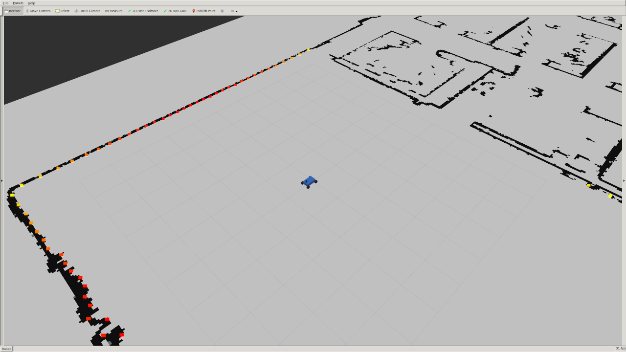
You can move the car around by plugging in a joystick into your computer, or by clicking the "2D Pose Estimate" button on top of rviz and dragging somewhere on the map.
Note that the simulator does not include collision detection, but we will check that your car has not crashed.
In order to make the car drive autonomously you will need to publish messages of type AckermannDriveStamped to the /drive topic.
Import the AckermannDriveStamped type like this in your wall_follower.py file:
from ackermann_msgs.msg import AckermannDriveStamped
The racecar (and its simulation) are equipped a with LIDAR sensor that measures the distance from the racecar to its surroundings with high accuracy. All of the LIDAR data is published to the /scan topic.
The data is of type LaserScan. You can import the type in python using:
from sensor_msgs.msg import LaserScan
The ranges data entry in the LaserScan message is an array of the distances from the lidar sensor to the nearest obstacle. The measurements are taken at regular intervals, angle_increment, from the angle angle_min to the angle angle_max.
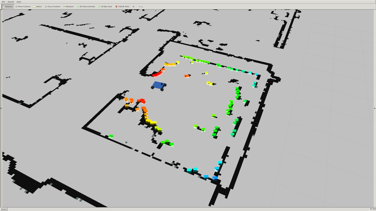
The rainbow points in this image below are the laser scan as visualized in rviz. The color simply corresponds to the intensity of the scan. In the simulator this is simply the distance, but on the actual lidar it gives you an indication of how reflective the object you are scanning is. Note that there is no data in the quadrant behind the car because the LIDAR sensor does not scan the full 360 degree range.
The simulator uses a number of parameters that might be useful for your wall follower including:
max_speed: 4 meters/secondmax_steering_angle: 0.34 radians
A complete list can be found in the simulator's params.yaml. Don't change these parameters, they will be automatically reset to defaults when you run the automated test suite anyways.
How you implement the wall follower is entirely up to you. However implementing the following may get you started in the right direction:
- Set up ROS structure: Set up your wall follower node so that it subscribes to laser messages and publishes steering commands. Make sure you can at least make the racecar move fowards at a constant speed and turning angle before working on your controller.
- Slice up the scan: Consider slicing the
rangesdata into more useful pieces. A majority of the data won’t be useful to you if you only care about a wall to one side. When you can, try to usenumpyoperations rather than for loops in your code. Multidimensional slicing and broadcasting can make your code cleaner and much more efficient. You can turn any array into anumpyarray withnp.array, or you can integrate it directly with ros like in this tutorial. - Find the wall: There are many ways to detect a wall in a laser scan. In a perfect world you might be able to detect it using a single sample of the LIDAR data. However with noisy data and uneven surfaces this might not be enough. A least squares regression is an easy way to account for more noise. The RANSAC algorithm can “upgrade” an existing model (like least squares) to be more robust to outliers. Note: Attempt RANSAC only if you've already built a functional wall follower. It is probably overkill.
- Use PD or PID control: A robust wall follower algorithm that can handle wavy wall contours and corners should probably use some sort of PD or PID control. Simple P (proportional) control is often not enough to create a responsive and stable system.
- Use the visualization code: We provided an example Python script in
srcthat plots a line in Rviz. Try to use this to make sure your code (e.g. wall detection) is working!
Since we are providing you with a series of automated tests for your wall follower, we ask that you use the starter code contained in this repo and do not tweak its original structure.
Make sure that your wall follower lives in the ROS node initialized in the Python script at:
src/wall_follower.py
However, if you want to add more Python files to keep your code organized, feel free to do so.
You must use the following ROS parameters in your follower:
desired_distance: The distance, in meters, that the racecar should maintain from the wallvelocity: The speed the racecar should move in meters per second.side: The side the wall is following represented as an integer. +1 represents the left wall and -1 represents the right wall. We chose this convention because typically we will assume the car is pointing in the positive x direction. That means the left side of the car will point to the positive y axis and the right side will point to the negative y axis.
The test cases will vary these parameters, so you must use them to pass.
The default values of these parameters are stored in the params.yaml file.
To launch the wall follower, run:
roslaunch wall_follower wall_follower.launch
The test suite runs on entirely on its own and puts your racecar through some basic wall following challenges.
Our test will override the values for desired_distance, velocity, and side that are set in the params.yaml file in order to make sure they are being used correctly.
You can download the test binary by going to the releases page of this repo and downloading the run_tests binary (testsv2). Make the binary executable with chmod:
chmod +x run_tests
-
Kill all running ROS processes.
-
Start
roscore. -
If you wish to the see the racecar executing the tests, you can also start
rviz. -
Run the following in a new terminal to begin testing:
./run_tests
Notes:
-
As the racecar completes each challege,
run_testswill write to a file namedlog.npz. Upload this file to Gradescope, where it will be automatically graded. -
If you kill the test script before you complete all of the challenges, the ones that have completed so far can still be graded.
-
If your racecar takes too long (i.e. it gets lost or crashes), the challenge will eventually time out and move to the next one.
-
You can also run individual tests by running:
./run_tests [Test Number]To have a particular test case scored, your racecar must successfully drive from the start point where we automatically place it, to a specified end area (see video below for example).
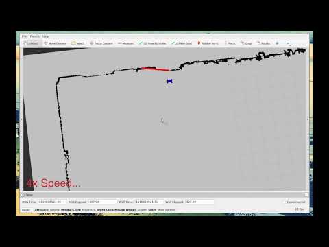
Click on the video below to see a full run of the tests.
Note that roscore and rviz are already running in the two stacked windows on the left.
In our implimentation we draw a red line in rviz using the Marker message to visualize the wall that we have detected. You will be required to make useful visualizations like these in future labs. If you are having issues debugging your system it can be much easier to recognize the problem if you can visualize the output, so feel free to try to do so in this lab and ask the TAs if you need help.
In each test case we compute distances from the racecar to the wall on the appropriate side at regular time intervals. If your code is truly following a wall than it should minimize the average absolute difference between the distance to the wall and the desired distance to the wall.

To turn this value into a score between 0 and 1 we compute:

Don't worry, it is impossible to get exactly 100%.
In some test cases we start the racecar closer or farther to the wall than the desired distance, which will automatically lower the max score.
The racecar also has to navigate around tight turns which it can't do perfectly with a limited turning radius.
Moreover there are many ways to measure the distance to a wall so our metric might not match yours exactly.
We have chosen , so your score will be in the high 90's for most of the tests.
Your score for the
short_left_far_angled test will be lower than the others because the racecar starts far from the desired distance. Example TA grades below:

Tampering with the autograder or the submission file and hardcoding solutions to the test cases will be considered cheating. Don't do it.