ESPHome component to monitor a Victron device (MPPT, SmarShunt, BMV, Phoenix Inverter ... ) via ve.direct / UART TTL
All Victron devices providing a ve.direct port.
-
Victron SmartSolar MPPT 75/15
-
Victron SmartSolar MPPT 100/15
-
Victron SmartSolar MPPT 100/20
-
Victron BlueSolar MPPT 100/30
-
Victron SmartSolar MPPT 150/35
-
Victron SmartSolar MPPT 150/45
-
Victron SmartSolar MPPT 150/60
-
Victron SmartSolar MPPT VE.Can 150/100 rev2 (Using VE.Direct port)
-
Victron SmartSolar MPPT 250/70
-
Victron Phoenix Inverter 12/500
-
Victron Blue Smart IP65 Charger 12|25
-
Victron SmartShunt 500A/50mV
- ESPHome 2024.6.0 or higher.
- Generic ESP32 or ESP8266 board
Attention: The TX voltage of the VE.Direct interface depends on the product: Some are 5V, others 3.3V!
Please measure the voltage between TX and GND. In case of a logic level of 5V you should add a voltage divider or logic level converter between the ESP and the Victron device.
                UART-TTL
┌────────────────┐                ┌──────────────────┐
│           GND o│<-------------->│o GND             │
│ Victron    TX o│--------------->│o D7   ESP32/     │
│ Charger    RX o│                │       ESP8266    │<-- GND
│            5V o│                │                  │<-- 3.3V
└────────────────┘                └──────────────────┘

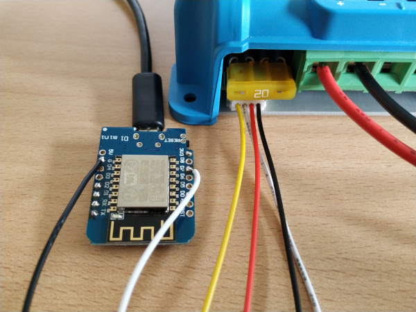
# UART-TTL jack (JST-PH 2.0mm pinch)
┌─── ─────── ────┐
│                │
│ O   O   O   O  │
│GND  RX  TX VCC │
└────────────────┘
If you are unsure about to pin order please measure the voltage between GND and VCC (5V). If you measure a positive voltage you know the position of VCC and GND!
| Pin | Purpose | ESP8266 pin | ESP32 pin |
|---|---|---|---|
| 1 | GND | GND | GND |
| 2 | RX | ||
| 3 | TX | D7 (RX) | GPIO16 (RX) |
| 4 | 5V |

note: JST-PH connector on this image has lock downwards

note: Level shifter (5V<->3.3V)between esp32 and mppt is not necessary (tested on esp32 nodemcu v1 and MPPT 75/115 , MPPT 150/35 and smartshunt 500A)
use ADUM 1201 for galvanic isolation between ESP and Victron Devices (or make an insulated cable for Ve.direct)
You can install this component with ESPHome external components feature like this:
external_components:
  - source: github://KinDR007/VictronMPPT-ESPHOME@main

uart:
  id: uart_0
  tx_pin: D8  # Not used! The communication is read-only
  rx_pin: D7
  baud_rate: 19200
  rx_buffer_size: 256

victron:
  id: victron0
  uart_id: uart_0

sensor:
  - platform: victron
    victron_id: victron0
    panel_voltage:
      name: "Panel voltage"
    battery_voltage:
      name: "Battery voltage"
    battery_current:
      name: "Battery current"
or just use the esp8266-example.yaml as proof of concept:
# Install esphome
pip3 install esphome

# Clone this external component
git clone https://github.com/KinDR007/VictronMPPT-ESPHOME.git
cd VictronMPPT-ESPHOME

# Create a secret.yaml containing some setup specific secrets
cat > secrets.yaml <<EOF
mqtt_host: MY_MQTT_HOST
mqtt_username: MY_MQTT_USERNAME
mqtt_password: MY_MQTT_PASSWORD

wifi_ssid: MY_WIFI_SSID
wifi_password: MY_WIFI_PASSWORD
EOF

# Validate the configuration, create a binary, upload it, and start logs
esphome run esp8266-example.yaml
The uart_id and victron_id is optional if you use a single UART / victron device. All sensors are optional.
The victron device pushs one status message per second. To reduce the update interval of the ESPHome entities please use the throttle parameter to discard some messages.
| Label | Sensor name |
|---|---|
| LOAD | load_state |
| Relay | relay_state |
| Label | Sensor name |
|---|---|
| AC_OUT_V | ac_out_voltage |
| AC_OUT_I | ac_out_current |
| AC_OUT_S | ac_out_apparent_power |
| CE | consumed_amp_hours |
| CS | charging_mode_id |
| DM | midpoint_deviation_of_the_battery_bank |
| ERR | error_code |
| HSDS | day_number |
| MPPT | tracking_mode_id |
| I | battery_current |
| I2 | battery_current_2 |
| I3 | battery_current_3 |
| IL | load_current |
| MODE | device_mode_id |
| MON | dc_monitor_mode_id |
| OR | off_reason_bitmask |
| P | instantaneous_power |
| PPV | panel_power |
| SOC | state_of_charge |
| T | battery_temperature |
| TTG | time_to_go |
| VPV | panel_voltage |
| V | battery_voltage |
| V2 | battery_voltage_2 |
| V3 | battery_voltage_3 |
| VM | midpoint_voltage_of_the_battery_bank |
| VS | auxiliary_battery_voltage |
| WARN | warning_code |
| H1 | depth_of_the_deepest_discharge |
| H2 | depth_of_the_last_discharge |
| H3 | depth_of_the_average_discharge |
| H4 | number_of_charge_cycles |
| H5 | number_of_full_discharges |
| H6 | cumulative_amp_hours_drawn |
| H7 | min_battery_voltage |
| H8 | max_battery_voltage |
| H9 | last_full_charge |
| H10 | number_of_automatic_synchronizations |
| H11 | number_of_low_main_voltage_alarms |
| H12 | number_of_high_main_voltage_alarms |
| H13 | number_of_low_auxiliary_voltage_alarms |
| H14 | number_of_high_auxiliary_voltage_alarms |
| H15 | min_auxiliary_battery_voltage |
| H16 | max_auxiliary_battery_voltage |
| H17 | amount_of_discharged_energy |
| H18 | amount_of_charged_energy |
| H19 | yield_total |
| H20 | yield_today |
| H21 | max_power_today |
| H22 | yield_yesterday |
| H23 | max_power_yesterday |
| Label | Sensor name |
|---|---|
| Alarm | alarm_condition_active |
| AR | alarm_reason |
| BMV | model_description |
| CS | charging_mode |
| ERR | error |
| FW | firmware_version |
| FWE | firmware_version_24bit |
| HC# | hardware_revision |
| MODE | device_mode |
| MON | dc_monitor_mode |
| MPPT | tracking_mode |
| OR | off_reason |
| PID | device_type |
| WARN | warning |
| SER# | serial_number |
If this component doesn't work out of the box for your device please flash the debug-esp8266-example.yaml and create an issue providing the full ESPHome log.
esphome run debug-esp8266-example.yaml
Big thanks for help to ssieb for the support!

