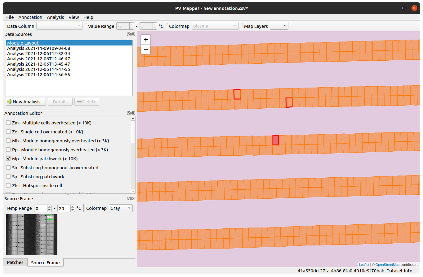
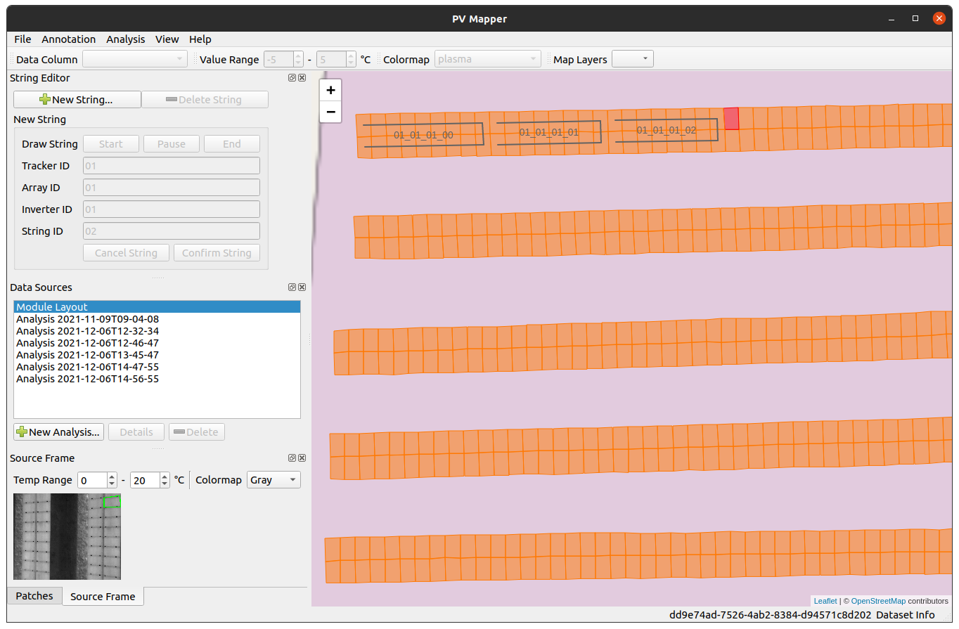
This is an open-source desktop app for viewing and analyzing maps of large-scale photovoltaic (PV) plants created with PV Hawk.
The app provides the following functionality:
- View the reconstruction of your PV plant created with PV Hawk
- Browse individual PV modules and video frames
- Perform analyses (e.g. PV module defect detection)
- Overlay analysis results on the map
- Annotate PV module defects
- Annotate electrcial connectivity of modules (strings)
This app requires Python 3 to be installed on your machine.
We recommend installing the Dataset Viewer for PV Hawk in a Python virtual environment, which you can create with the following command in a new terminal
python3 -m venv env
On Linux and macOS, you can activate the enviroment with
source env/bin/activate
on Windows type
.\env\Scripts\activate
Inside the activated environment upgrade pip
python3 -m pip install --upgrade pip
and then install the dataset viewer via pip
python3 -m pip install --upgrade PV-Hawk-Viewer
Note, that depending on your platform you will have to replace python3 with python or py in the commands above.
After successful installation you can start the dataset viewer simply by typing in the terminal
viewer
Note, that to start the dataset viewer, you will always have to activate the Python virtual environment first.
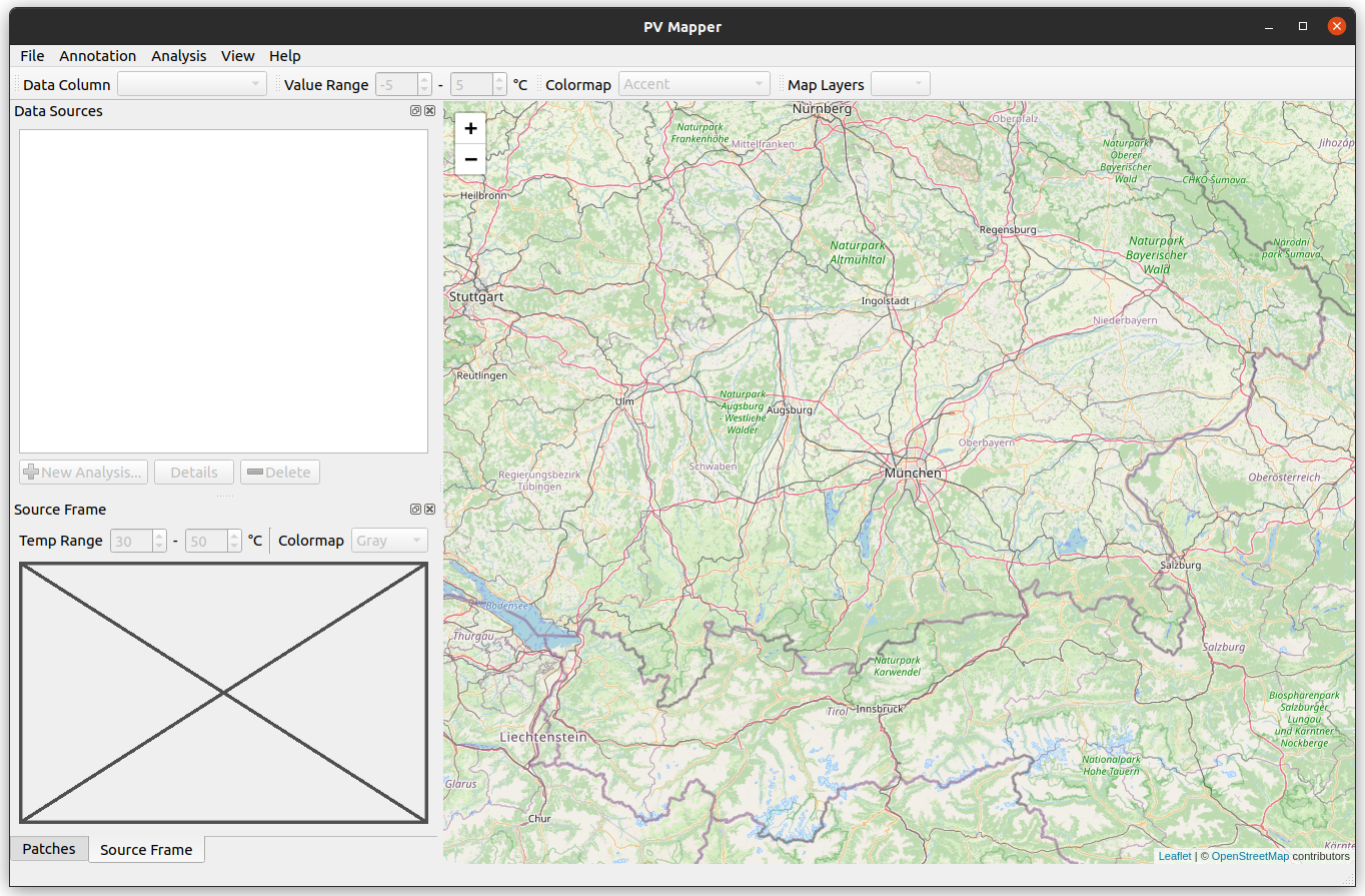
After startup the app shows an empty map.
You can download an example dataset from here (part 1, part 2, part 3, part 4, part 5). This dataset corresponds to the output generated in the PV Hawk tutorial. Due to file size limitations of GitHub, the dataset is split into multiple parts. After downloading all the parts, you have to first combine them into a single zip archive and then unzip them into a single directory with the following commands
zip -F example_data_double_row_reconstructed.zip --out example_data_double_row_reconstructed_full.zip
unzip example_data_double_row_reconstructed_full.zip
You can then open this dataset in PV Hawk Viewer as outlined in the next section.
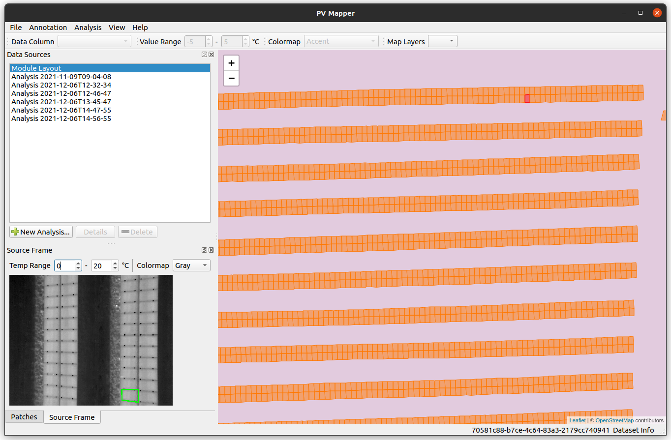
First, you have to open a PV Hawk dataset by clicking File -> Open Dataset.... When the dataset is loaded correctly the map updates and shows a map of the PV plant. You can click individual PV modules and the app will retrieve all image patches of that module as well as the video frame of which the first patch was extracted.
Note, that you may have to set the gain and offset for conversion of raw image values into Celsius scala. If the values are wrong, you may not be able to see the infrared video frame when clicking onto a PV module. You can modify the gain and offset values under File -> Dataset Settings. Please refer to the manual of your thermal camera for the respective values. Default values are 0.04 for the gain and -273.15 for the offset and are suitable for the example dataset.
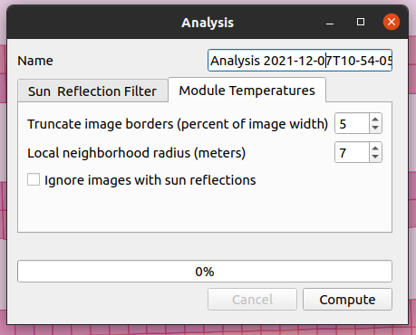
The app provides some analyses that can be performed on the dataset. To this end, click Analysis -> New Analysis... The window below will open. Here, you can select which analysis to perform. You can set the hyper parameters and run the analysis by clicking Compute. See below for details on the available analyses.
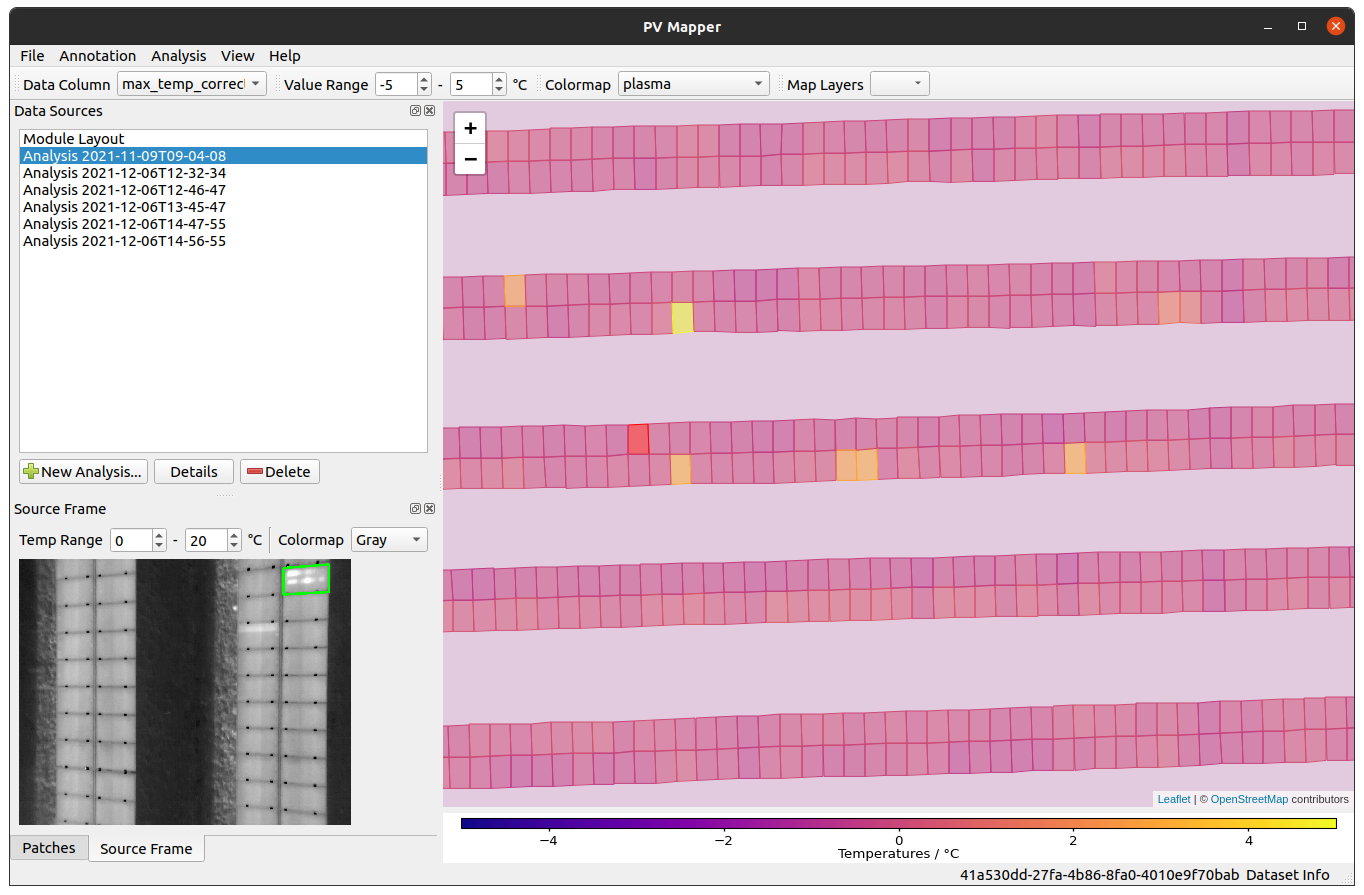
Once the analysis is completed, you will find an entry in the Data Sources list. When you click on this entry, the map will update and show the analysis results, e.g. temperatures of the PV modules as shown below.
Results are stored for each analysis under <path to the opened dataset>/analyses/<name of the analysis>.
You can use the dataset viewer to manually annotate each PV module with one or multiple defect classes. To this end, click Annotation -> New Defect Annotation... An additional Annotation Editor list will become visible.
To label a module click onto the module in the map and then check the checkboxes with the corresponding defect class(es) in the Annotation Editor. You can save the annotation via Annotation -> Save Defect Annotation
You may also provide your own annotation scheme by editing the existing scheme in src/resources/defect_schema.json.
The dataset viewer finally allows you to annotate the electrical connectivity of the individual PV modules. To do so, click on Annotation -> Annotate Strings... An additional String Editor widget will become visible.
To enter a new string click New String... in the string editor. Now, you will have to draw lines into the map which connect all modules within a string. For this, click the Start button and on the map click on the first module in the string. If your string is a simple line you can click onto the last module on the map and then hit the End button to stop drawing. All modules intersecting the line will be assigned to that string.
If your string is not a simple line, you have to draw multiple line segments. Instead of clicking only the first and last module in a string, click on those intermediate modules where you want to start a new line segment.
If you encouter a situation where a string contains modules at different (far apart) locations in the plant, you can click the Pause button while drawing the line segments. This allows you to draw a line segment which does not include intersecting modules in the string.
After hitting the End button provide the Tracker ID, Array ID, Inverter ID and String ID and hit Confirm String. This will assign a unique ID to each module which looks as follows <Tracker ID>_<Array_ID>_<Inverter ID>_<String_ID>_<Module ID>. The module ID is automatically created based on the location of the module along the line that you drew ealier.
You can export the string annotation for further use by clicking Annotation -> Export String Annotation...
As mentioned above the dataset viewer allows you to perform some analyses on the PV Hawk dataset. We will explain those in more detail here.
Depending on the camera angle during filming the sun may be reflected in the inspected PV modules. This disturbs downstream defect detection. The sun reflection filter identifies which of the images extracted of a PV module contains a sun reflection so that they can be ignored during other analyses.
To this end, the filter eploits the non-stationarity of the sun reflection in the module images extracted from subsequent video frames. The filter works as follows:
First, the filter finds the maximum temperature Temperature Threshold) and $||(x_i − \bar{x}, y_i − \bar{y})||2 > 10$ px (Location threshold). The reference values $\bar{T}$ and $(\bar{x}, \bar{y})$ are median values computed from a subsequence of the patches which is obtained as follows. First, the discrete difference $p{i+1} − p_i$ of the Euclidean norm Changepoint Threshold). All zero-subsequences of Segment Length Threshold) are obtained (the longest is used if none exceeds
The four highlighted threshold values can be specified in the app before running the sun reflection filter.
Please see section IV.H in our paper for further information about the sun reflection filter.
The module temperature analysis computes various module temperatures from the extracted infrared image patches allowing to quickly identify defective modules.
Specifically, for each image patch the minimum, maximum, median and mean temperature are computed over the entire image area. The mean is taken over all patches of the same PV module to obtain a single scalar temperature value for each module. In the Data Column combo box in the toolbar you can select which of the temperatures to visualize on the map.
Prior to computing the temperatures, the border of each patch is cropped to reduce the effect of mounting brackets and the module frame. You can specify the amount to crop with the Truncate image borders hyper parameter.
To remove the global trend in the temperature distribution over the entire PV plant, additional 'corrected' temperatures are computed. To compute, for example, the corrected maximum temperature of a module, the algorithm subtracts the median value of the maximum temperatures of all neighbouring modules from the maximum temperature of that particular module. All modules within a circle of the radius specified by the Local neighborhood radius hyper parameter are considered neighbors.
You can also choose to ignore all patches with sun reflections by checking the Ignore patches with sun reflections checkbox. This option is only available if you run the sun reflection filter beforehand.
This software is written by Lukas Bommes, M.Sc. - Helmholtz Institute Erlangen-Nürnberg for Renewable Energy (HI ERN)
This project is licensed under the MIT License - see the LICENSE file for details.
If you use PV Hawk or the Dataset Viewer for PV Hawk in your research please consider citing our works listed here.
