    ________  _______  __    _____       ______
   /  _/ __ )/ ____/ |/ /   / ___/____  / ____/
   / // __  / __/  |   /    \__ \/ __ \/ /
 _/ // /_/ / /___ /   |    ___/ / /_/ / /___
/___/_____/_____//_/|_|   /____/\____/\____/
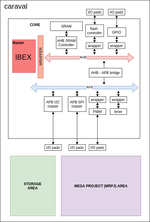
This is an SoC based on IBEX, a riscV based core, built for Digital Design 2 Course @ AUC, to be submitted and manufactured by Google Shuttle.
It is designed entirely using open source EDA tools ....
Design and process flow are detailed below
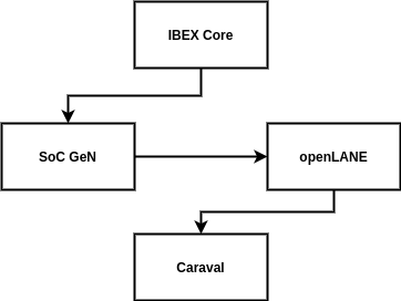
Just like the designing tools, the entire project is manfactured using opensource cores.
- IBEX Core
- AHB - APB bidge and system from SoC GeN, discuessed in details in the tools section
- IPs from SoC GeN
- Caravel, a template SoC for Google SKY130 free shuttles
In the IBEX Core repo, the entrie system is designed using SystemVerilog (IEEE 1800-2017). However, due to using iverilog and yosys for compilation and synthesis, we needed to convert it to Verilog (IEEE 1364-2005).
Fortunately, IBEX repo includes a script to perform this conversion using sv2v
To perfom the conversion you would need to go to the /util directoty inside IBEX repo. Then, you would need to insert the path of the standered cell library. In our project, in order to fit the Shuttle spacifications, we used the opensource SKY130A standrad cell library ... more detail on this in latter sections.
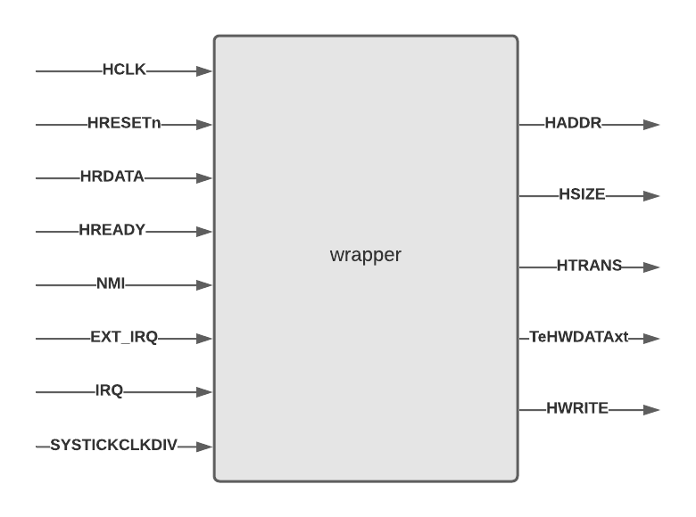
Also, our SoC is supposed to communicate with other components through AHB Bus Interface. So, we designed a wrapper to make our system compatible with AHB standard signals.
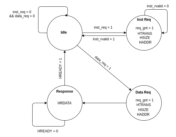
The wrapper's main mission was producing AHB compatible signals from our IBEX core. We did this through instantiating the core inside our wrapper and mapped its signals to AHB signals through the following FSM:
It mainly has four states:
- idle
- data request
- instruction request
- waiting for the response
here is a quick description of the main AHB signals:
| Signal | Description |
|---|---|
| HCLK | clock singal |
| HRESETn | reset signal |
| HADDR | the address to be used for the transfer |
| HSIZE | indicates the size of a data transfer. 000 => byte 001 => Half word 010 => word |
| HTRANS | state of the transfare 00 => idle 01 => busy 10 => NON SEQUENTIAL |
| HREADY | indicates previous transfer is complete |
| HRDATA | The slave output to the master |
| HWRITE | enable write to slaves |
| HWDATA | data to be written in slave |
you can find the full description of IBEX signals in their documentation
you details of each signal could be found in the
new wrapper.vin our src folder.
Special thanks to our professor @shalan for helping us with it.
Aside from IBEX core, the entire SoC is generated using SoC GeN. In order to generate the system, a description of the systems signals must be inserted in the "masters.json" file in SoC Gen. Then you would need to add a description of the needed SoC and the connected subsystems. You can find our work under .....
Then, you can generate the sytem using this command :
node ./src/sys_gen.js -soc ./systems/IBEX/Demo/demo.json -subsystem ./systems/IBEX/Demo/apb.json -IPlib ./IPs/IPs.json -mastersLib ./masters/masters.json -outDir ./IBEX/
Along with the generated system, SoC GeN generates a self checking testbench to test the entire system. in order to run them and view the result, you would need:
- Icarus Verilog
- GTKwave
- Prebuilt RISC‑V GCC Toolchain from SiFive
to run the testbenchs, run the following commands in order:
find . -name "*.v" > file.lst
iverilog -o ./ibex_system.vvp -c file.lst
vvp ibex_system.vvp
gtkwave real_dump.vcd
More on our test results in the test section
As detailed in openLANE's documentations, each design needs a config file. So, we wrote our config file to make our hardened MACROS compatible with Caravel, and to reach the optimal hardening results.
The config file is included in **** directory
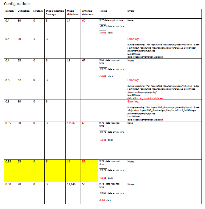
we did some experimentations on the config.tcl file to find out the optimum configuration settings which produce lower violations and positive slack. You can find different configurations trials in MS2 "Report.pdf" where we have a table with different options and the corresponding results.
Notes:
● All the magic violations are false positives because they are minimum hole violations.
● Going below 3.5 for PL_TARGET_DENSITY configuration or setting SYNTH_STRATEGY to 1 result in segmentation violation.
● Since, segmentation violation is not a descriptive error, so the error is hard to be figured out. Setting PL_TARGET_DENSITY to 3.5 and SYNTH_STRATEGY to 1 should be avoided.
● The best combination of configurations is highlighted.
● In the last configurations combination, the negative slack has been reduced by 0.05. However, the false positive antenna violations increased dramatically. This trial had the least utilization, produced the least slack, but generated dramatic magic violations. So, a trade-off has to be made here between targeting lowering the slack and lowering the violations.
● The trade-off we made targeted the least violations. We chose the best combinations that produce the least violations. We can increase the system clock to produce a positive slack.
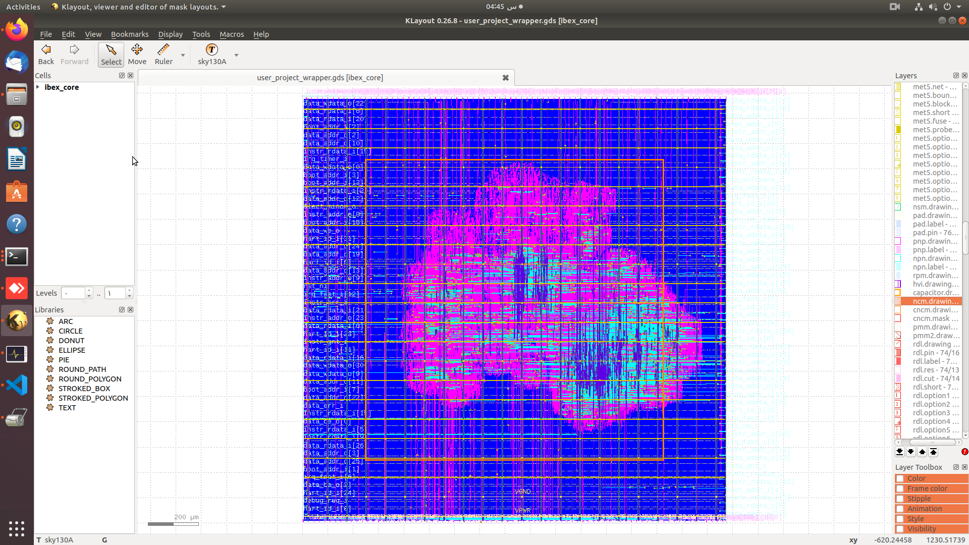
● To address the magic violations produced in the last run, we are currently trying different diode insertion strategies.
just like the output of any hardened design using openlane, this was the structure of the output:
designs/IBEX_SoC
├── config.tcl
├── pdn.tcl
├── pin_order.cfg
├── src
|   ├── src files ...
├── runs
│   ├── <tag>
│   │   ├── config.tcl
│   │   ├── logs
│   │   │   ├── cts
│   │   │   ├── floorplan
│   │   │   ├── magic
│   │   │   ├── placement
│   │   │   ├── routing
│   │   │   └── synthesis
│   │   ├── reports
│   │   │   ├── cts
│   │   │   ├── floorplan
│   │   │   ├── magic
│   │   │   ├── placement
│   │   │   ├── routing
│   │   │   └── synthesis
│   │   ├── results
│   │   │   ├── cts
│   │   │   ├── floorplan
│   │   │   ├── magic
│   │   │   ├── placement
│   │   │   ├── routing
│   │   │   └── synthesis
│   │   └── tmp
│   │       ├── cts
│   │       ├── floorplan
│   │       ├── magic
│   │       ├── placement
│   │       ├── routing
│   │       └── synthesis
Getting started
We started by cloning the repo and uncompressing the files.
git clone https://github.com/efabless/caravel.git
cd caravel
make uncompress
Then we installed the required version of the PDK as well as Magic VLSI Layout Tool to run open_pdks -- version >= 8.3.60 To install PDK we used the following commands:
export PDK_ROOT=<The place where you want to install the pdk>
make pdk
We put our user_project_wrapper.gds under ./gds/ in the Caravel directory. Inside Caravel we export the following:
export PDK_ROOT=<The location where the pdk is installed>
export OPENLANE_ROOT=<the absolute path to the openlane directory cloned or to be cloned>
export IMAGE_NAME=<the openlane image name installed on your machine. Preferably openlane:rc6>
export CARAVEL_PATH=$(pwd)
Then, we mount the docker:
docker run -it -v $CARAVEL_PATH:$CARAVEL_PATH -v $OPENLANE_ROOT:/openLANE_flow -v $PDK_ROOT:$PDK_ROOT -e CARAVEL_PATH=$CARAVEL_PATH -e PDK_ROOT=$PDK_ROOT -u $(id -u $USER):$(id -g $USER) $IMAGE_NAME
Finally, once inside the docker we run the following commands:
cd $CARAVEL_PATH
make
exit
As spacified by Caravel's documentation, our project is inserted into user_project_wrapper sub-directory. Then, the hardened SoC MACRO is integered with the caravel template.
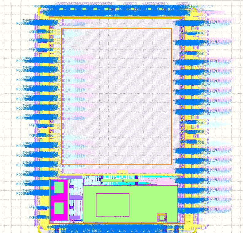
here is an image from the hardened caravel before inseting our design:
NOTE: currently, caravel is a WIP, so there is a number of magic DRC with the final output.
Our design was tested by the self-checking testbench generated by SoC Gen. It was basically reading riscV instructions and performing reading from memory, perfoming operation over the data, and writing back to memory.
here is a sample of the test result:
Mem request (0) A:0000069c
Mem request (0) A:0000068c
Mem request (0) A:2000fff8
Mem request (0) A:00000690
Mem request (0) A:00000694
Mem request (1) A:2000fff8
PWM Test Passed
The result of the entire test is included in the /tests sub-directory.
SoCGen included a number of systems and N5-based-SoC was the closest to our IBEX-based-SoC. So, we used it as a golden model to check the correction of our model.
Here is a screenshot of the waveform generated by our system:
to view the tests, just follow the steps mentioned in the Generating the SoC Section
