The goals / steps of this project are the following:
- Compute the camera calibration matrix and distortion coefficients given a set of chessboard images.
- Apply a distortion correction to raw images.
- Use color transforms, gradients, etc., to create a thresholded binary image.
- Apply a perspective transform to rectify binary image ("birds-eye view").
- Detect lane pixels and fit to find the lane boundary.
- Determine the curvature of the lane and vehicle position with respect to center.
- Warp the detected lane boundaries back onto the original image.
- Output visual display of the lane boundaries and numerical estimation of lane curvature and vehicle position.
To run the lane detection pipeline on an image (.jpg) or video (.mp4), call runner.py -p <path/to/image/or/video>. runner.py is a high-level script that handles command line input and outlines the major steps required for lane detection by calling relevant helper functions in utils.py. The real meat of the code resides in utils.py, and frequently-used constants are defined in constants.py.
Rubric Points
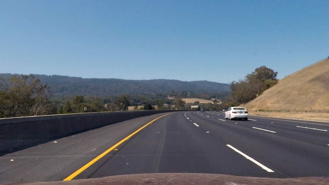
Here I will consider the rubric points individually and describe how I addressed each point in my implementation. I will show examples of each stage applied to the given image test3.jpg.
###Writeup
####1. Provide a Writeup / README that includes all the rubric points and how you addressed each one. You can submit your writeup as markdown or pdf. Here is a template writeup for this project you can use as a guide and a starting point.
You're reading it! ###Camera Calibration
####1. Briefly state how you computed the camera matrix and distortion coefficients. Provide an example of a distortion corrected calibration image.
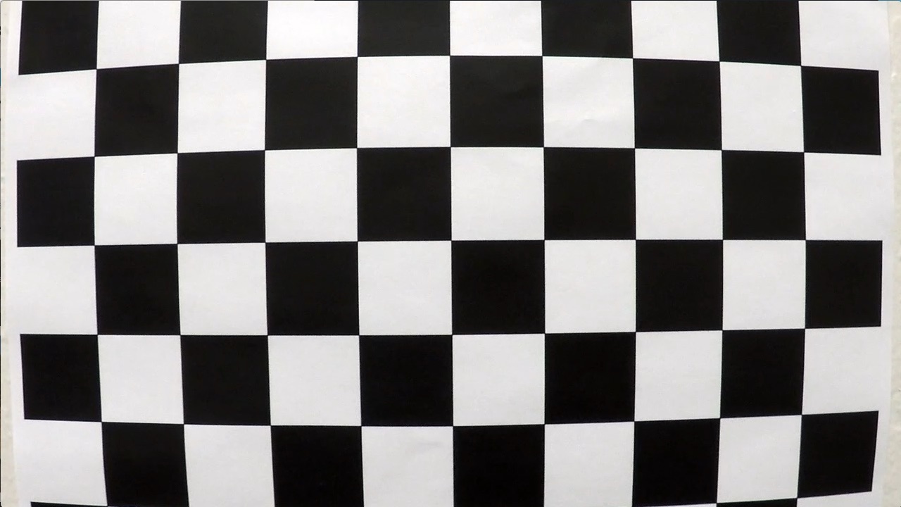
I calibrate the camera using given distorted images of a chessboard and the cv2.findChessboardCorners() function. I start by preparing "object points", which will be the (x, y, z) coordinates of the chessboard corners in the world. Here I am assuming the chessboard is fixed on the (x, y) plane at z=0, such that the object points are the same for each calibration image. Thus, obj_points_const is just a replicated array of coordinates, and obj_points will be appended with a copy of it every time I successfully detect all chessboard corners in a test image. img_points will be appended with the (x, y) pixel position of each of the corners in the image plane with each successful chessboard detection.
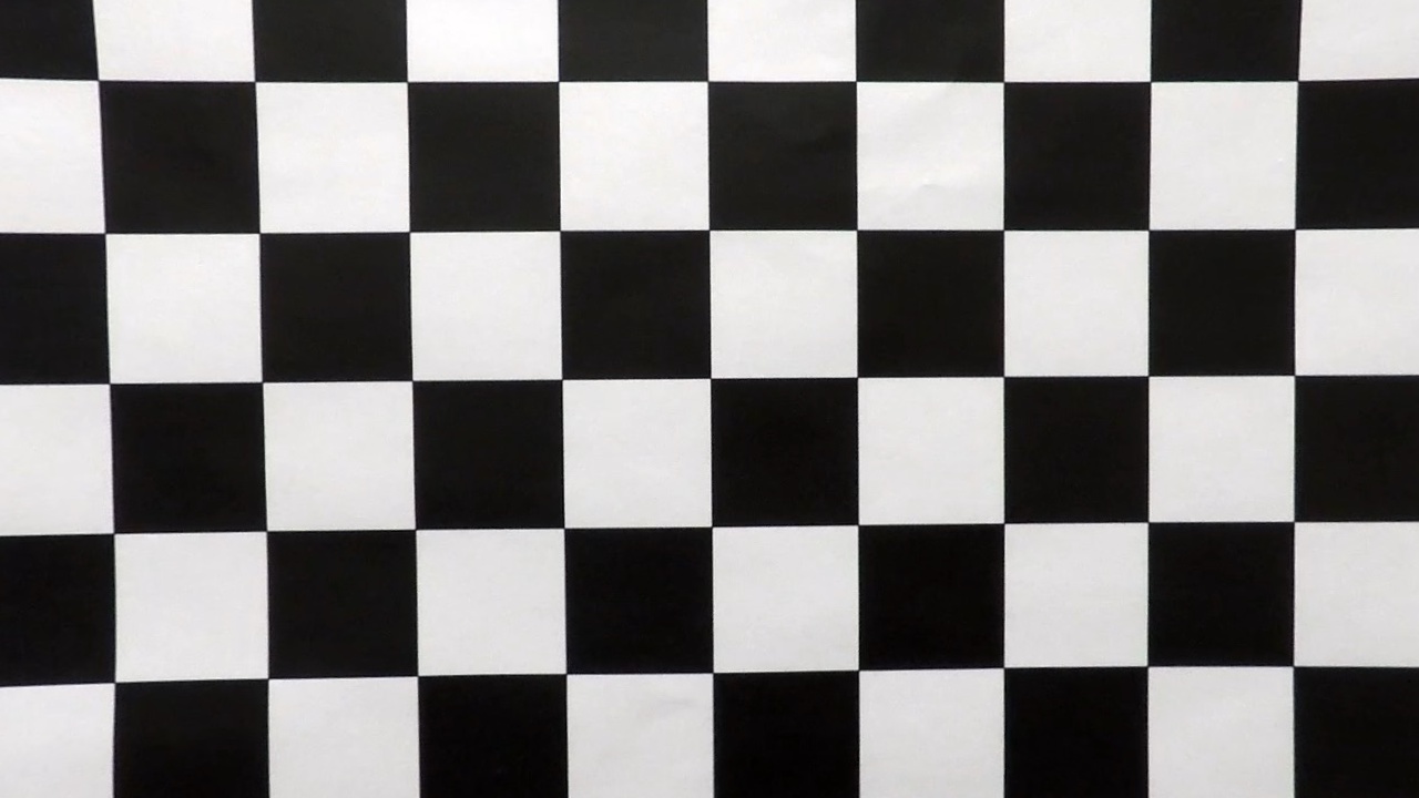
I then use the output obj_points and img_points to compute the camera calibration and distortion coefficients using the cv2.calibrateCamera() function. I applied this distortion correction to the test image using the cv2.undistort() function and obtained this result:
Original image:
Undistorted image:
###Pipeline (single images)
####1. Provide an example of a distortion-corrected image.
To correct the distortion of road images, I use the function undistort_imgs() at line 132 of utils.py. This function uses cv2.undistort() with the camera matrix and distortion coefficients calculated during camera calibration to return undistorted versions of all input images.
test3.jpg before correction:
test3.jpg after correction:
####2. Describe how (and identify where in your code) you used color transforms, gradients or other methods to create a thresholded binary image. Provide an example of a binary image result.
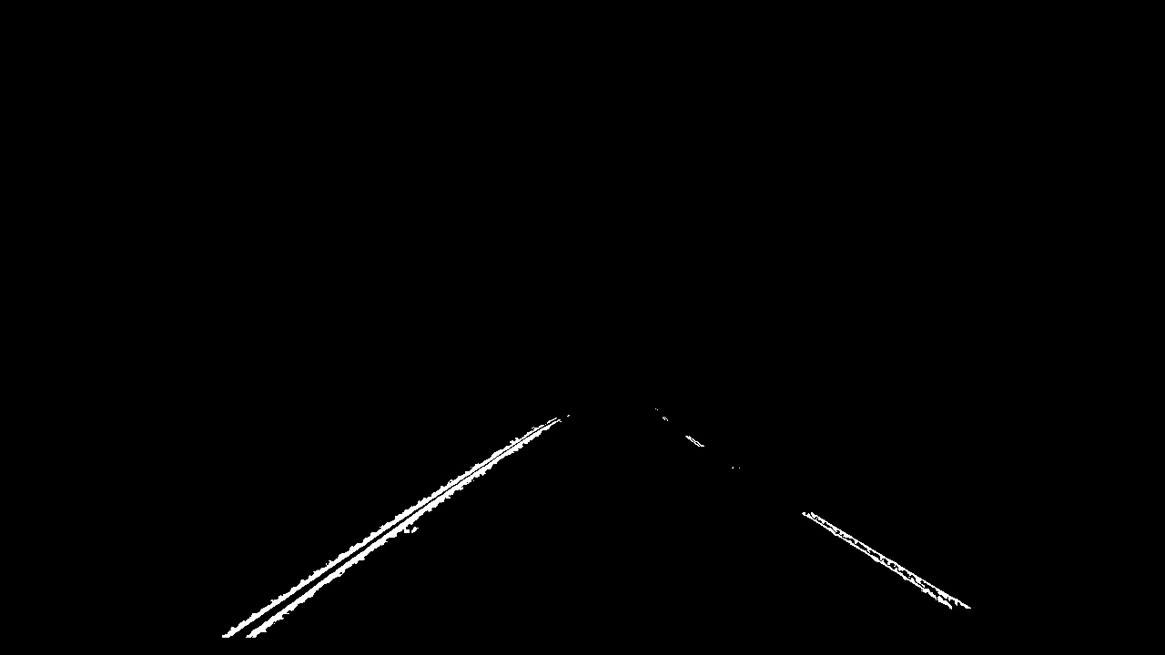
I use a combination of geometric, color and gradient masking to generate a binary image (thresholding steps at lines 149 through 323 in utils.py).
As a geometric mask, I use the functions quad_mask() and tri_anti_mask() at lines 177 and 206, respectively, in utils.py. quad_mask() keeps everything within a trapezoidal region where lane lines are likely to exist. This helps to remove lines caused by cars in other lanes and scenery. tri_anti_mask() removes everything within a small triangle near the bottom center of the image. This helps to remove lines caused by shadows and cracks in the middle of the lane.
To create a color mask, I used the function color_mask() at line 233 in utils.py. color_mask() uses the hue, saturation and grayscale channels of the image, as these were the color channels that had the clearest distinction of lane line vs. road, even in varying light conditions. Values between (100, 255), (15, 70) and (190, 255) are kept for each of the respective channels, and the final color mask is a combination of any pixel within any of the thresholds.
To create a gradient mask, I use the function grad_mask() at line 281 in utils.py. I calculate the Sobel gradient in the x direction on saturation and grascale channels. I use a Sobel kernel size of 7 to smooth the results. Values between (30, 255) and (50, 255) are kept for each of the respective channels, and, like the color mask, all pixels in either channel mask are combined into the final gradient mask.
The final mask applied to the image is a logical and of the geometric, color and gradient masks – keeping only the pixels that exist in all three. This occurs in get_masks at line 308 of utils.py.
Here's an example of my output for this step:
####3. Describe how (and identify where in your code) you performed a perspective transform and provide an example of a transformed image.
The code for my perspective transform includes a function called birdseye(), which appears in lines 326 through 351 in utils.py. birdseye() takes images as inputs and uses a source and destination mapping (SRC and DST from constants.py) to map from the original perspective to a birdseye view of the image. I calculated SRC by picking points from one of the provided images with straight lane lines (straight_lines1.jpg) and mapped this to a rectangular DST.
This resulted in the following source and destination points:
| SRC | DST |
|---|---|
| 257, 685 | 200, 720 |
| 1050, 685 | 1080, 720 |
| 583, 460 | 200, 0 |
| 702, 460 | 1080, 0 |
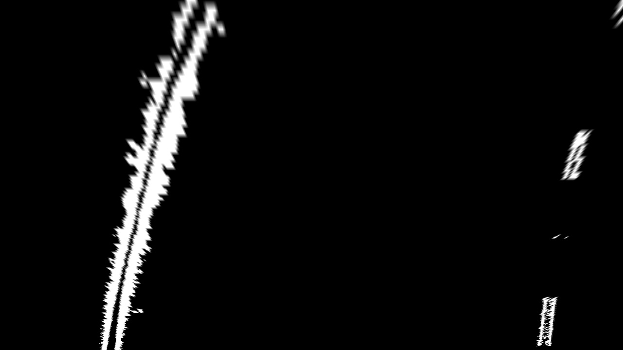
I verified that my perspective transform was working as expected by verifying that the lane lines appear parallel in the warped images:
####4. Describe how (and identify where in your code) you identified lane-line pixels and fit their positions with a polynomial?
To identify lane line pixels in the perspective transformed mask, I initially use hist_search() at line 434 of utils.py. hist_search() uses a sliding window histogram of the pixel values to select pixels around the two peaks (one for each line). For videos, I also use local_search(), which selects pixels around the previously-found lines. This helps keep the lines more stable when there is more noise in the masks. I use the following priority to decide which method to use:
- First, try get the lines from a local search based on past lines found. If those lines are good, use them.
- If good lines were found in the last 5 frames, use the most recent good lines found.
- Do a naive histogram search. If those lines are good, use them.
- Otherwise, use the last good fit found, regardless of time.
When a good fit cannot be found using either local or histogram search, and the algorithm must fall back on a previous fit, I display red text on the frame. This helps measure where the search algorithms fail.
After selecting the pixels, I fit a second-order polynomial to each line using np.polyfit() in my fit_line() function at line 377 of utils.py. I check if the detected lines are valid by making sure each horizontal pair of points on the left and right lines are within a certain range of pixels apars. This serves the dual purpose of checking if the lanes are a reasonable distance apart and if they are (roughly) parallel.
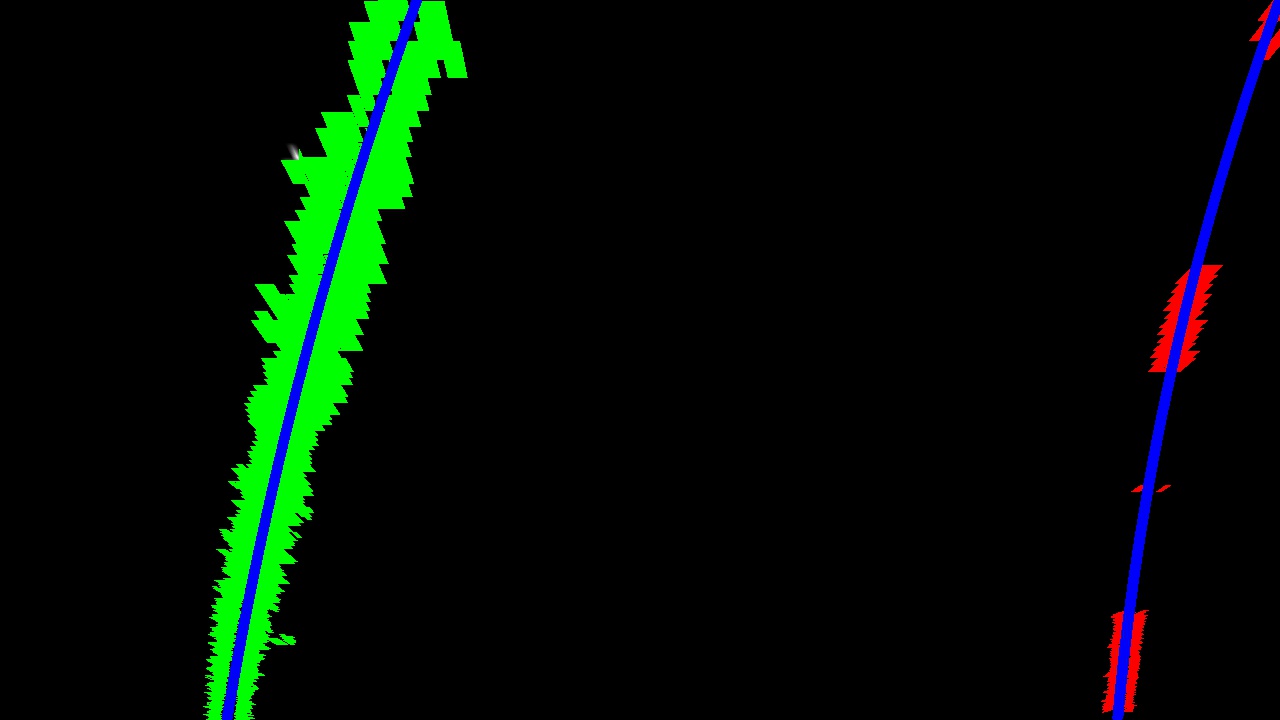
The following image shows the selected pixels and fitted polynomials for each line:
####5. Describe how (and identify where in your code) you calculated the radius of curvature of the lane and the position of the vehicle with respect to center.
I calculate the radius of curvature in get_curvature_radius() at line 396 of utils.py by averaging the curvature of the left and right lane lines. I calculate the position of the vehicle with respect to the center of the lane in draw_lane() at lines 670 to 679 in utils.py. I calculate this by measuring the distance from the center of the frame to the bottom of the left and right lines and taking the difference of those. In my code, negative distance represents that the car is to the left of center, while positive distance represents to the right.
####6. Provide an example image of your result plotted back down onto the road such that the lane area is identified clearly.
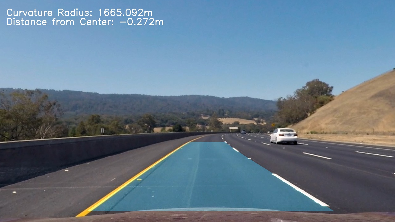
I implemented this step in draw_lane() at line 620 in utils.py. Here is an example of my result on a test image:
###Pipeline (video)
####1. Provide a link to your final video output. Your pipeline should perform reasonably well on the entire project video (wobbly lines are ok but no catastrophic failures that would cause the car to drive off the road!).
###Discussion
####1. Briefly discuss any problems / issues you faced in your implementation of this project. Where will your pipeline likely fail? What could you do to make it more robust?
My current pipeline does not work on the provided challenge video because some frames fail to find any pixels for one of the lane lines, and I am not sure what the best way to handle that case is. Having feeds from multiple cameras at different angles might help make lane lines always visible; Otherwise, we could assume thet the line is off the side of the frame and take everything to that edge as the lane, using only the line in view for curvature.
