The program STEPToXSection is a command line utility to export the contour of a planar cross section of solids contained in STEP files. It supports surface offsetting of the input geometry and in-plane curve offsetting. The in-plane base contour can also result from the orthogonal projection of geometries (silhouette) onto the plane within a specified maximum plane distance. The contour is a list of line segments. The supported output file formats are ply (edges, polygons, or triangles) and xyz. In the case of xyz, two consecutive vertices belong to the same edge. A popular viewer for the different file types is MeshLab (https://www.meshlab.net). STEPToXSection is based on OpenCASCADE (https://www.opencascade.com). The program uses cxxops (https://github.com/jarro2783/cxxopts) for parsing the command line.
Listing the contents (solids) of a STEP file:
STEPToXSection -c -i <step file>
Computing the planar cross section contour of the overall file content (solids):
STEPToXSection -i <step file> -o <output file> -d <deflection> -p <plane>
The parameter <deflection> controls the resolution of the approximation with line segments.
Computing the planar cross section contour of selected solids of the file:
STEPToXSection -i <step file> -o <output file> -d <deflection> -p <plane> -s <solid1>,<solid2>,<...>
In order to change the default output format ply (edges) the command line argument -f xyzhas to be specified.
Following the help text from the command line:
STEPToXSection.exe
Extracts a contour of the planar cross section of solids contained in STEP files. The programm supports surface offsetting of the input geometry and in-plane curve offsetting. The in-plane base contour can also result from the orthogonal projection of geometries (silhouette) onto the plane within a specified maximum plane distance.
Usage:
  STEPToXSection [OPTION...]

  -i, --in arg              Input file
  -o, --out arg             Output file
  -f, --format arg          Output file format (xyz, ply_edges, ply_polygons,
                            or ply_triangles) (default: ply_edges)
  -c, --content             List content (solids)
  -s, --select arg          Select solids by name or index (comma seperated
                            list, index starts with 1)
  -d, --deflection arg      Chordal tolerance used during discretization
  -p, --plane arg           Single plane (a,b,c,d) or parallel planes
                            (a,b,c,d_start,d_end,d_count), in which a*x + b*y + c*z +
                            d = 0
  -1, --surface_offset arg  Single offset (value) or range offset
                            (start,end,count) for surface offsetting of input geometry
  -2, --curve_offset arg    Single offset (value) or range offset
                            (start,end,count) for in-plane curve offsetting
  -n, --projection arg      Orthogonal projection of geometries with
                            specified maximum plane distance, in which the silhouette
                            of the projected geometries represents the
                            in-plane base contour
  -h, --help                Print usage
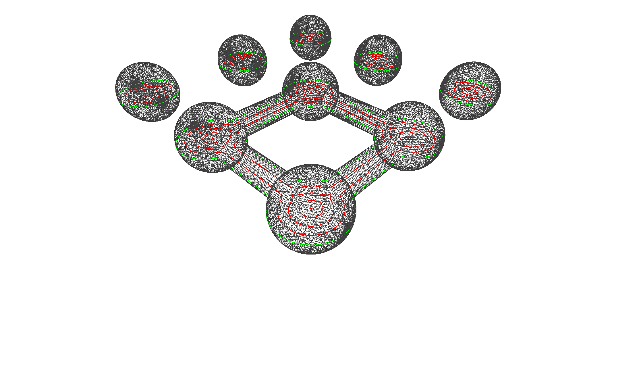
Examples spheres.stp and bone_pocket.stp are from the examples directory.
| Solids |
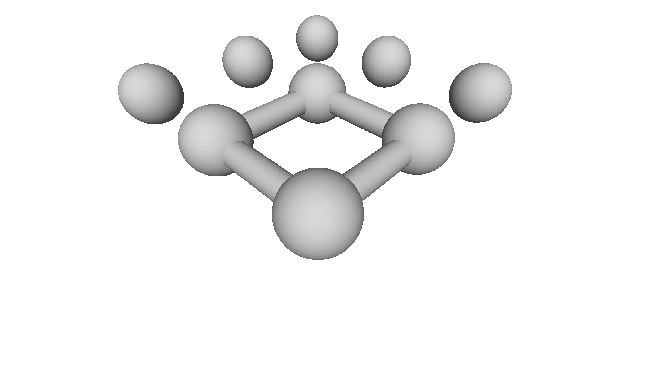 |
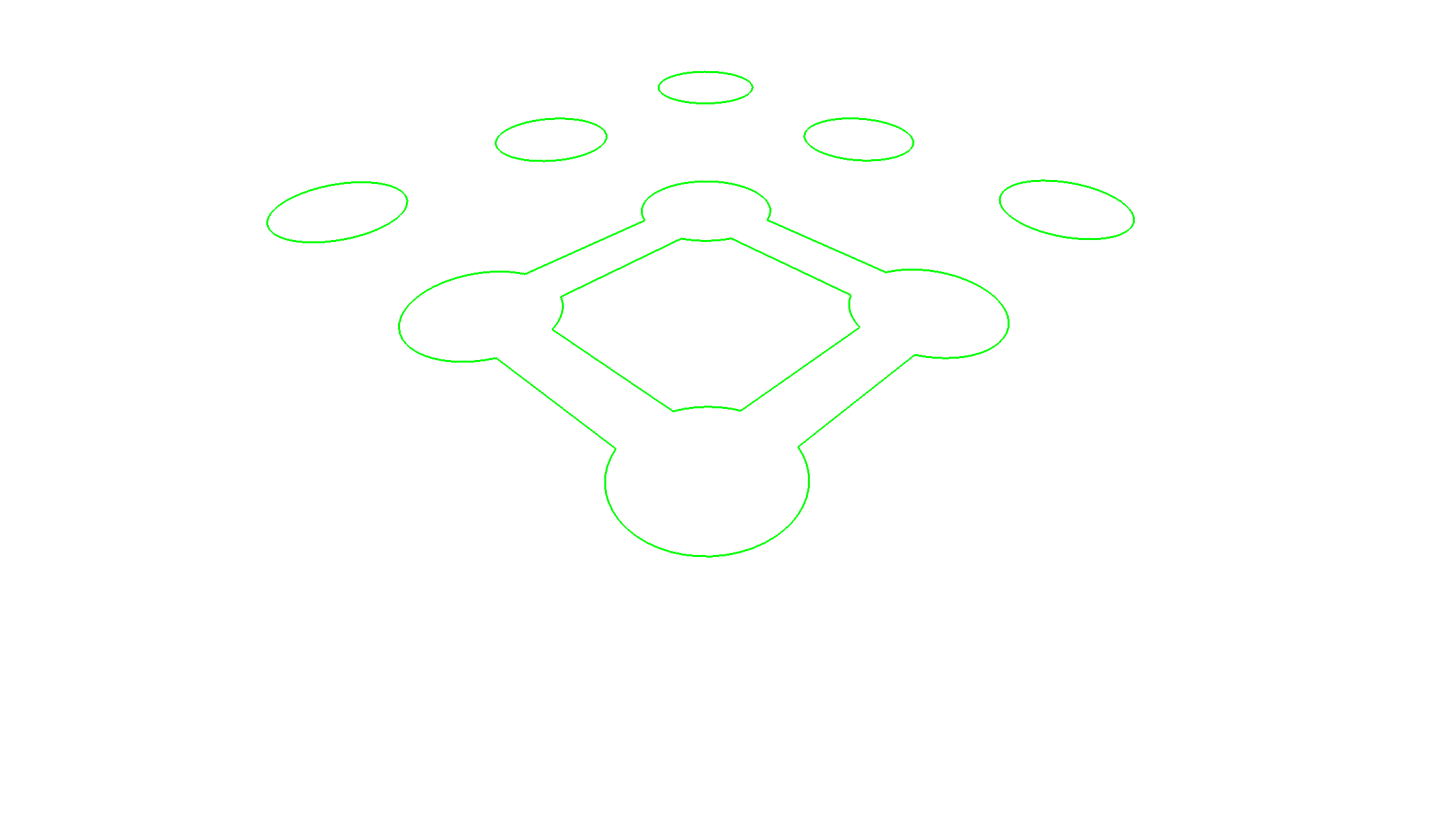
| Planar cross section |
STEPToXSection.exe -i spheres.stp -o out.ply -f ply_edges -d 0.01 -p 1.0,0.0,0.0,0.0 |
 |
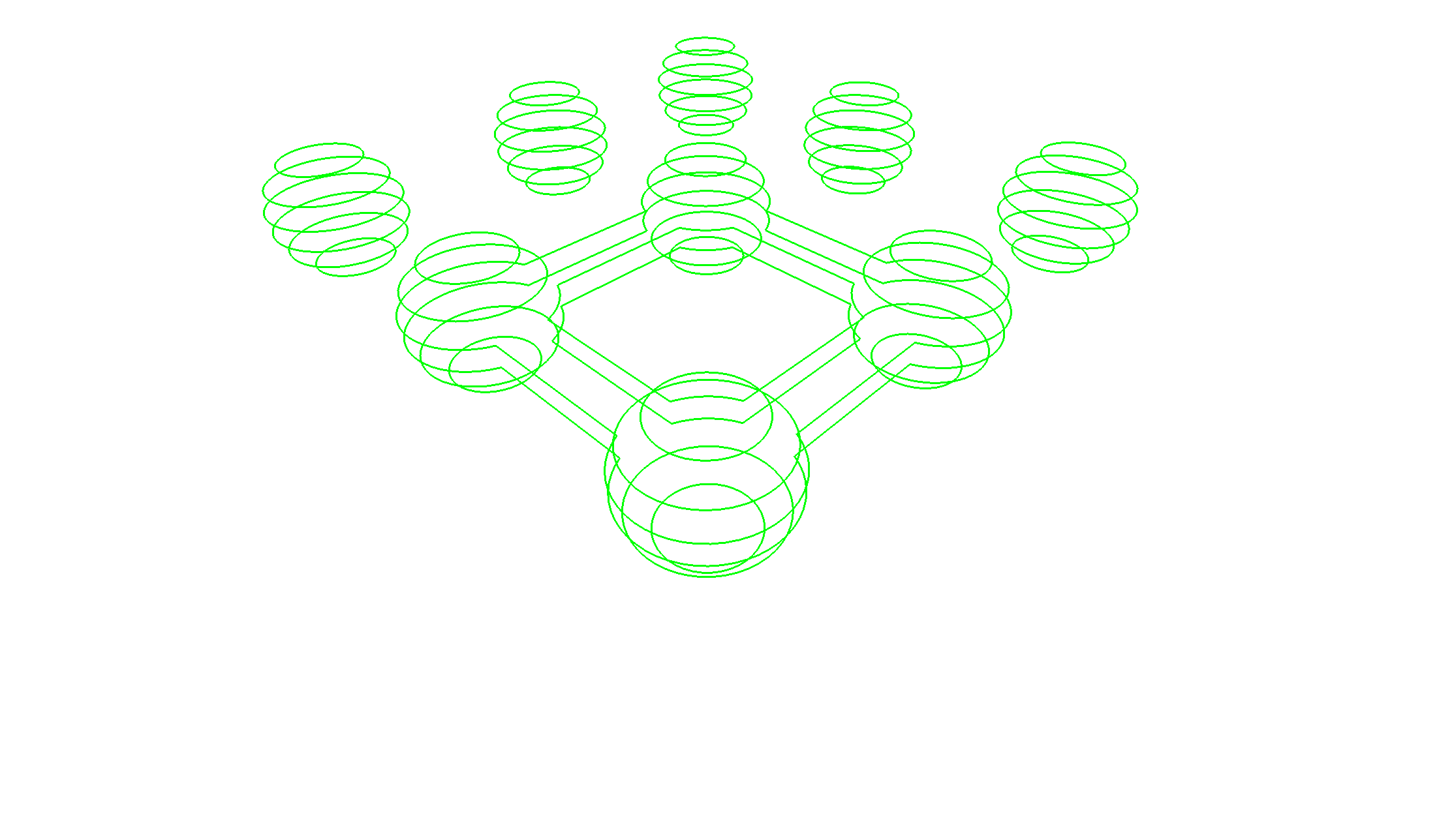
| Planar cross sections |
STEPToXSection.exe -i spheres.stp -o out.ply -f ply_edges -d 0.01 -p 1.0,0.0,0.0,-4.0,4.0,6 |
 |
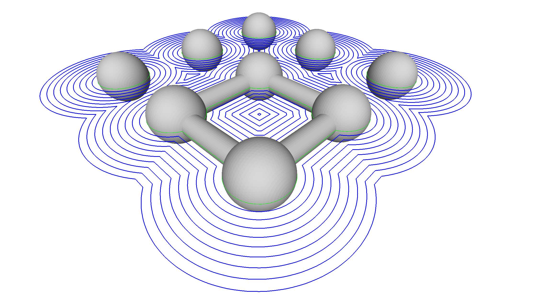
| Positive in-plane offset curves |
STEPToXSection.exe -i spheres.stp -o out.ply -f ply_edges -d 0.01 -p 1.0,0.0,0.0,0.0 -2 0.0,10.0,10 |
 |
| Negative in-plane offset curves |
STEPToXSection.exe -i spheres.stp -o out.ply -f ply_edges -d 0.01 -p 1.0,0.0,0.0,0.0 -2 0.0,-4.9,5 |
 |
| Solid |
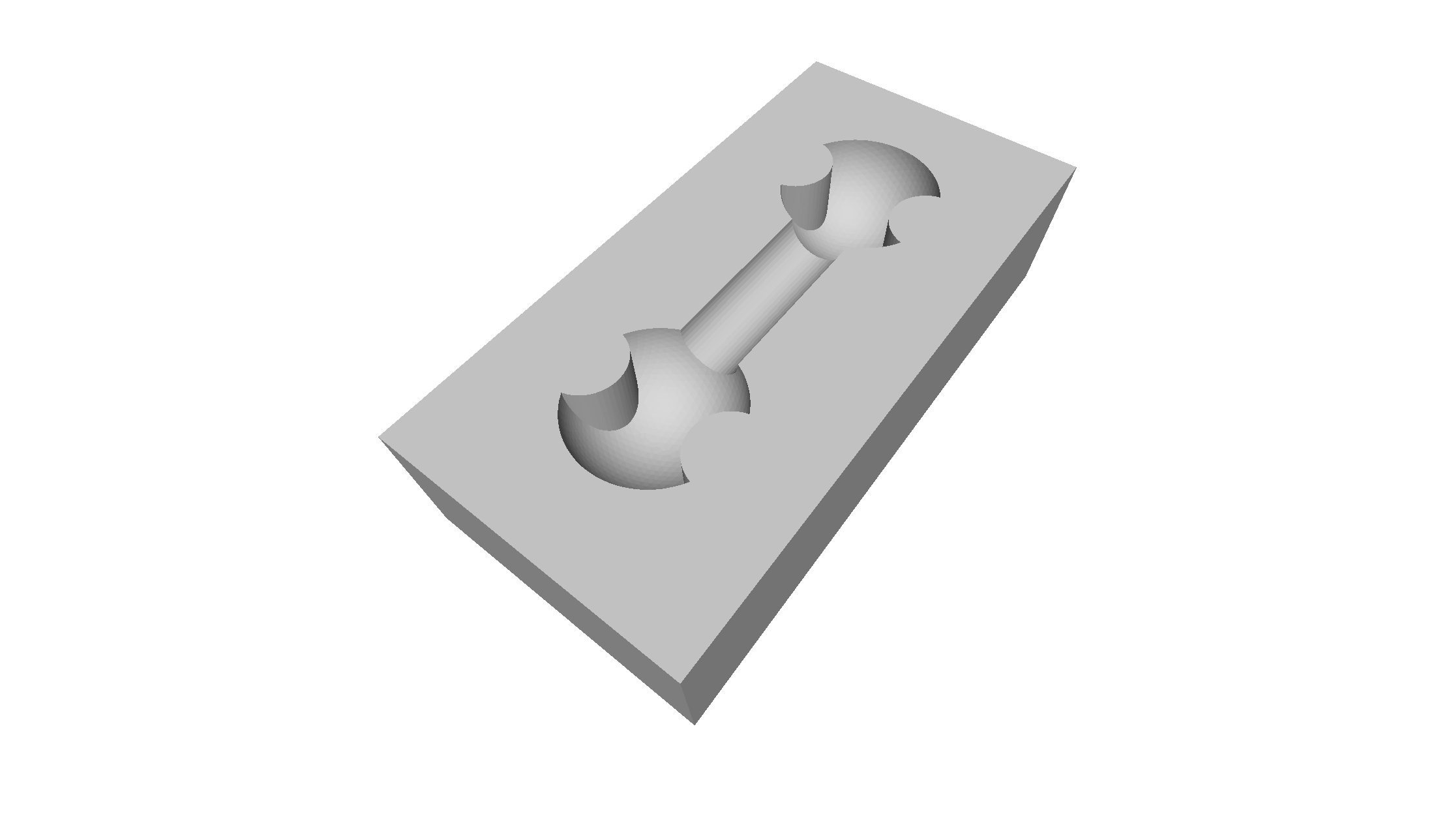 |
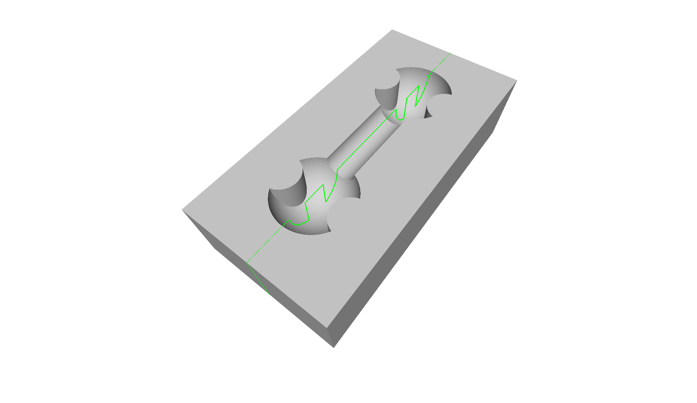
| Planar cross section |
STEPToXSection.exe -i Bone_Pocket.stp -o out.ply -f ply_edges -d 0.01 -p 0.0,0.0,1.0,0.0 |
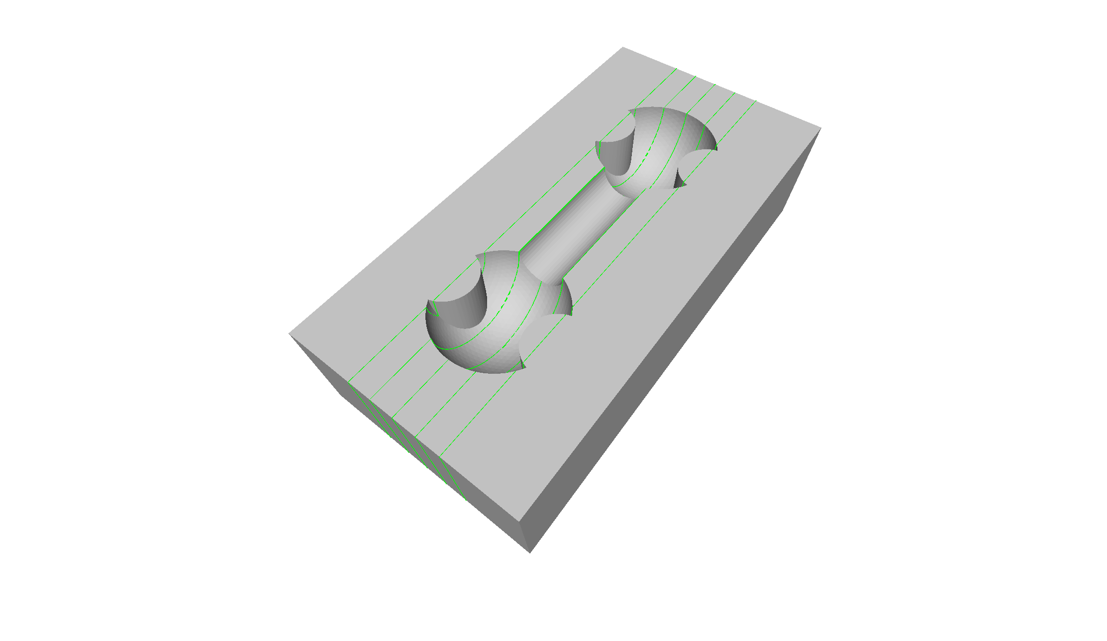
 |
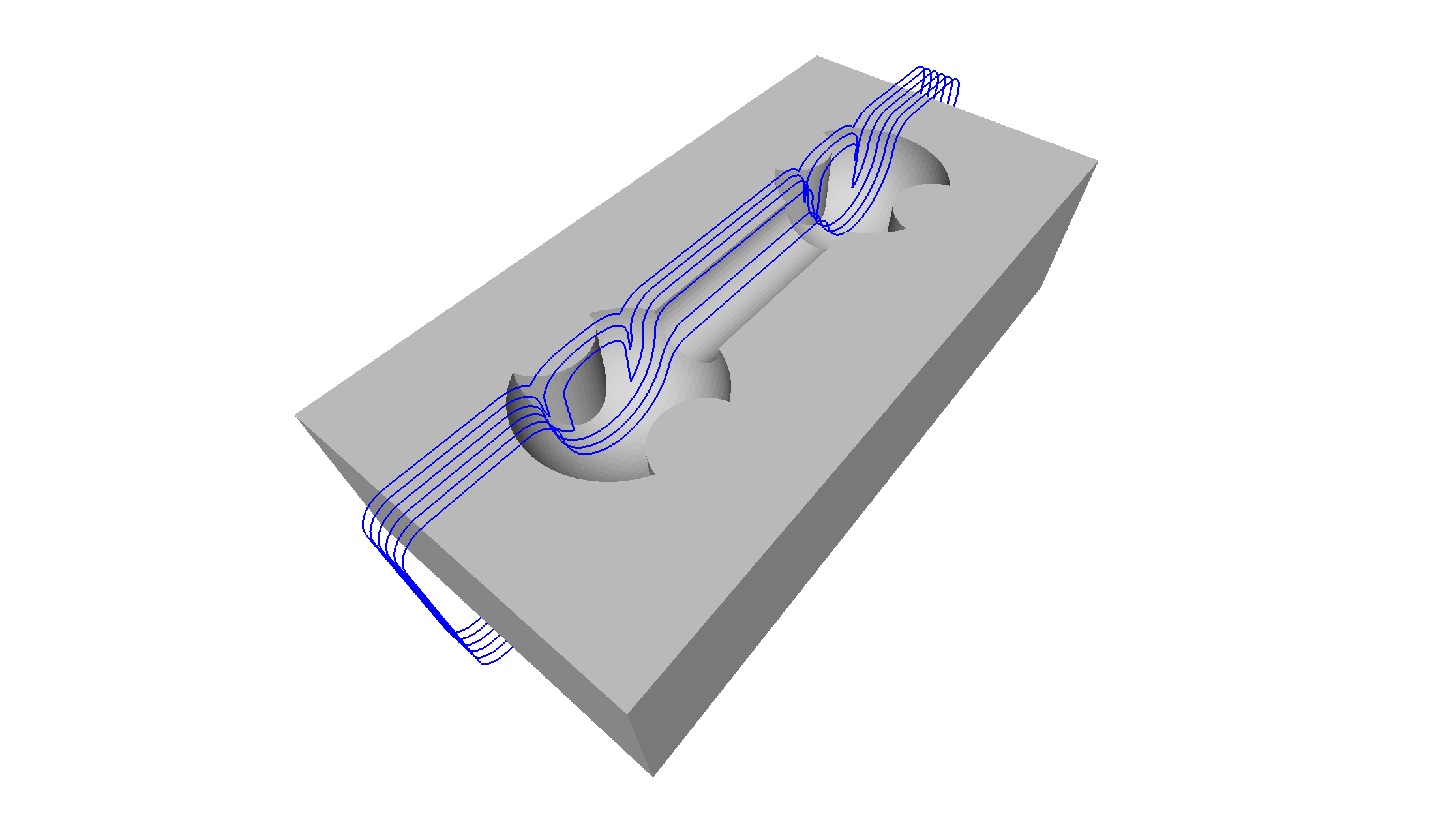
| Planar cross sections |
STEPToXSection.exe -i Bone_Pocket.stp -o out.ply -f ply_edges -d 0.01 -p 0.0,0.0,1.0,-4.0,4.0,5 |
 |
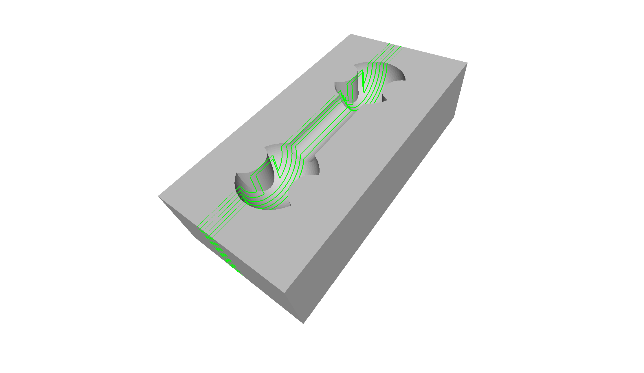
| Positive in-plane offset curves |
STEPToXSection.exe -i Bone_Pocket.stp -o out.ply -f ply_edges -d 0.01 -p 0.0,0.0,1.0,0.0 -2 0.0,4.0,5 |
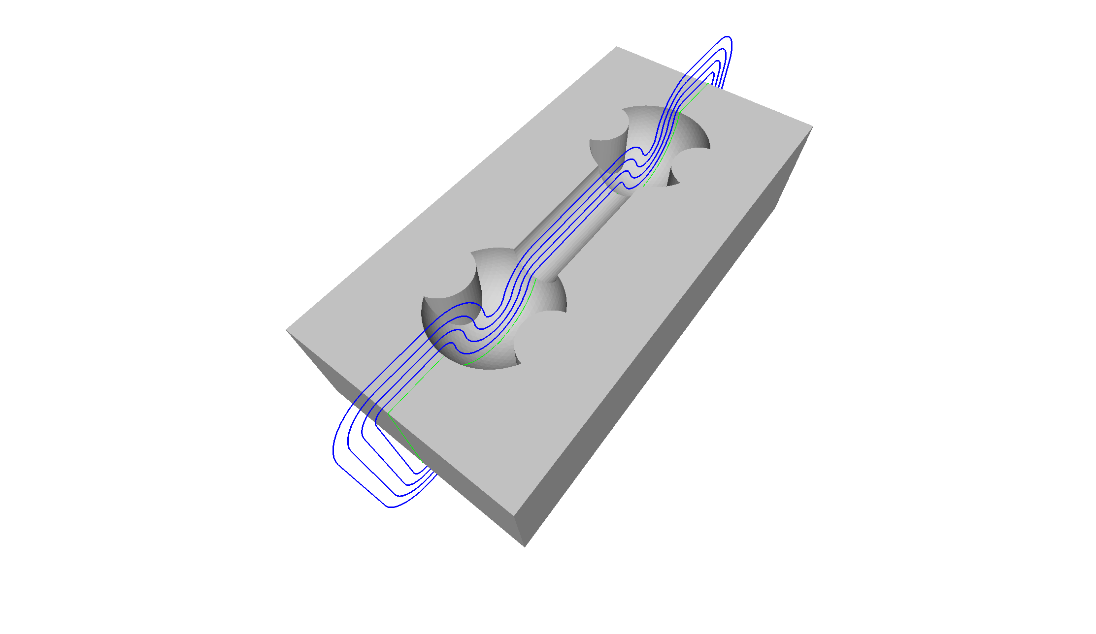 |
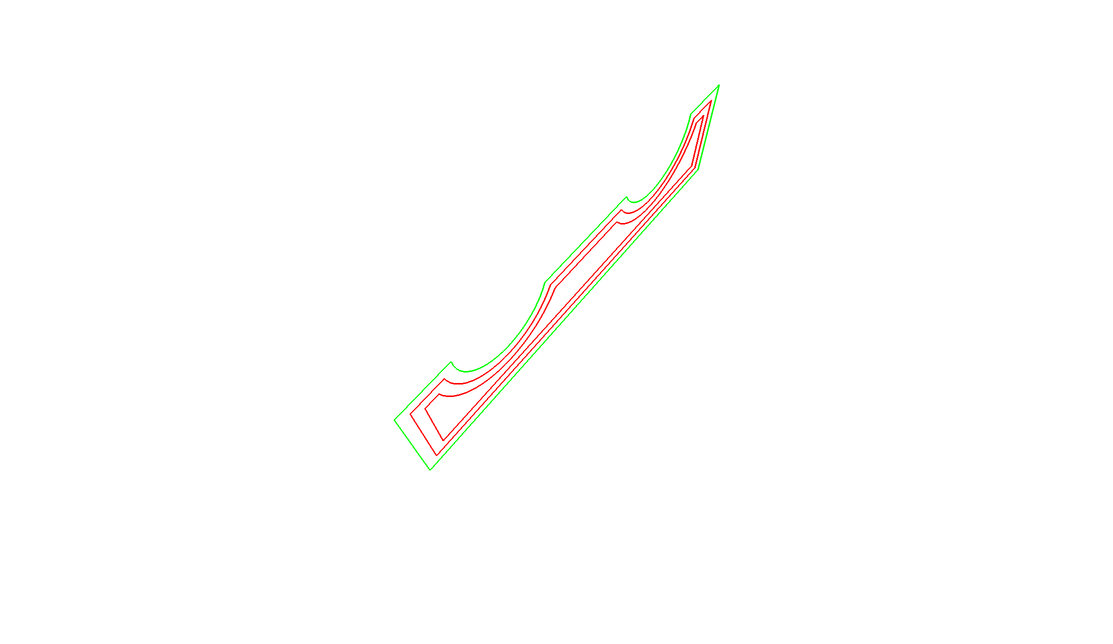
| Negative in-plane offset curves |
STEPToXSection.exe -i Bone_Pocket.stp -o out.ply -f ply_edges -d 0.01 -p 0.0,0.0,1.0,0.0 -2 0.0,-2.0,3 |
 |
| Silhouette of projected geometry within plane distance |
STEPToXSection.exe -i Bone_Pocket.stp -o out.ply -f ply_edges -d 0.01 -p 0.0,0.0,1.0,0.0 -n 3.0 |
 |
| Silhouettes of projected geometry within plane distance |
STEPToXSection.exe -i Bone_Pocket.stp -o out.ply -f ply_edges -d 0.01 -p 0.0,0.0,1.0,2.5,0.0,6 -n 1.0 |
 |
| Planar cross-sections using positive surface offset |
STEPToXSection.exe -i Bone_Pocket.stp -o out.ply -f ply_edges -d 0.01 -p 0.0,0.0,1.0,2.5,0.0,6 -1 1.5 |
 |
Remarks
This code has been tested with an OpenCASCADE 7.5.0 prebuilt binary (opencascade-7.5.0-vc14-64.exe) on Windows, as well as OpenCASCADE system packages on openSUSE Linux. With changes in the configuration section in the CMakeLists.txt file the build should also work with other OpenCASCADE versions.


