Note: This project is kept for historical reasons only. For my latest work on interfacing Raspberry Pi 3.5 inch TFT to ESP32 and STM32, browse to https://thehardcoder.weebly.com/driving-rpi-35-inch-tft.html
Interface a Raspberry Pi 3.5 inch LCD to an STM32F103C8T6 (blue pill) with stm32duino and SPI. The LCD normally plugs into the RPi's GPIO header(pin 1-26) via a short female header on the back of the display. But in this case, jumper wires are used to connect the 2 devices together. LCD driver software are used together with Arduino sketches to test and show the workings of the LCD.


The female header is numbered according to layout below(view from back of display). They correspond directly to the GPIO header pins on a Raspberry Pi board when plugged together.
  2   1
  4   3
  :   :
 26  25
| STM32 Pin | LCD Skt | Name |
|---|---|---|
| 5V | 2 | 5V |
| GND | 6 | GND |
| PA0 | 18 | RS |
| PA7 | 19 | MOSI |
| PA6 | 21 | MISO |
| PA1 | 22 | RST |
| PA5 | 23 | SCK |
| PA4 | 24 | CS0 |
| PA3 | 26 | CS1 |

The FTDI USB-serial adapter is only used for debug output.

Redirect Serial to Serial1 in the application sketches.
#define Serial Serial1
The STM32 is programmed using a cheap ST-Link device found in ebay.

- STM32duino is the official ST Arduino Core for the Maple Mini and other STM32 boards. See https://github.com/stm32duino/wiki/wiki/Getting-Started for installation details.
-You also need to download the STM32CubeProgrammer utility from ST website in order to upload sketches using ST-Link. - After installing ST core, configure IDE under Tools -> Board:
- Using the IDE Library Manager, install Waveshare ILI9486 SPI driver for Arduino.
- Change following lines in ...\libraries\Waveshare_ILI9486\src\DEV_Config.h to:
#define LCD_CS PA4
#define LCD_RST PA1
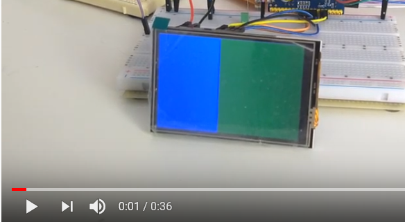
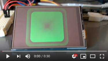
#define LCD_DC PA0 - Upload the sketch Examples -> Waveshare ILI9486 -> ws_graphicstest to the STM32. A test video is available below.

- This is the original STM32duino project by Roger Clark but has since been handed over to ST.
- It is recommended to use the official ST core though it is not as fast as the RC core but RC core is no longer actively maintained.
- See https://github.com/rogerclarkmelbourne/Arduino_STM32/wiki/Installation for RC core installation details.
- Latest update: The sketches below were developed under Roger Clarke's STM32 core which was the only one available back then. They will not work with the ST core. Try this new driver https://github.com/ImpulseAdventure/Waveshare_ILI9486 if you want to port the sketches to the ST core.
- helpful note from lazyan: clone of Waveshare 3.5 display needed an additional 3V on 1st pin (pin assigment according to your scheme) to turn on the backlight. Other connections are the same. Also there is new version of the display firmware (2.0) and no DEV_Config.h file there. All the pin setting are in Waveshare_ILI9486.cpp file. I could also suggest another addition to make touchscreen working: TP_CS = PA3
- Install from the Arduino IDE library manager.
- Clone https://github.com/alw1746/Adafruit_ILI9486_STM32 and unzip to your .../Arduino/libraries folder.
- Customise Adafruit_ILI9486_STM32.h according to your wiring diagram.
//Control pins |RS |CS |RST|
#define TFT_CNTRL GPIOA
#define TFT_RST PA1
#define TFT_RS PA0
#define TFT_CS PA4
- Clone https://github.com/alw1746/XPT2046_Touchscreen and unzip to your .../Arduino/libraries folder.
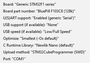
Configure the Arduino IDE with STLink as the upload method.
Board: Generic STM32F103C series
Variant: STM32F103C8 (20k RAM. 128k Flash)
CPU Speed(MHZ): 72Mhz (Normal)
Upload method: STLink
The sketches should be run in the following order to test and obtain information about the LCD.
-
graphicstest.ino - generate test patterns on the LCD. This verifies LCD-STM32 wiring is correct. If you get a white screen there is a mixup in the wiring, loose connections, insufficient power, etc.
-
LCDcalibrate.ino - obtain the screen boundary(x,y) and touch pressure(z) extrema of the LCD by poking the top left/bottom right corners of the LCD with low/high strength. Home(0,0) is the top left corner in landscape mode, X-axis is the top edge and Y-axis is the left edge. Change the pin definition if required:
#define CS_PIN PA3

-
TSpaint.ino - enhanced version of Adafruit's touchpaint for fun. Plug in values returned by the XPT2046 controller(from LCDcalibrate). The XY values are mapped by the code to pixel coordinates(480x320). Z values(pressure) are used to vary pen's stroke width. The heavier the pressure, the wider the stroke.
#define TS_CS_PIN PA3
#define TS_MINX 180
#define TS_MINY 250
#define TS_MAXX 3900
#define TS_MAXY 3900
#define TS_MINZ 800
#define TS_MAXZ 2000
