Set the voltage of a Quick Charge 3.0 source via Arduino.
By Vincent Deconinck
All credits go to :
- Hugatry's HackVlog because he came up with the idea and first code to control QC2.
- Timo Engelgeer (Septillion) who made a nice wrapper for Quick Charge 2.0: QC2Control. The QC3Control project is just a fork of QC2Control adapted for Quick Charge3 while retaining maximum compatibility so it can be used as a drop-in replacement.
QC3Control makes it possible to set the voltage (even on the fly) of a Quick Charge 3.0 source like a mains charger or power bank by simulating the behaviour of a QC3 portable device.
Of course, to take advantage of this library, the source needs to support the Quick Charge 3.0 technology form Qualcomm. However, the library can also be used with a QC2.0 compatible charger if using only set5V(), set9V(), set12V(), or setVoltage(5), setVoltage(9) or setVoltage(12).
QC3 chargers and battery packs should be backwards compatible with QC2, but I first had to adjust the resistor values compared to the ones in QC2Control. More information on my blog.
Apart from that, the main protocol difference between QC2.0 and QC3.0 is the introduction of continuous voltages, plus the possibility to lower the voltage to 3.6V.
To reach QC3.0 continuous mode, D- must be set high, which can be achieved two ways:
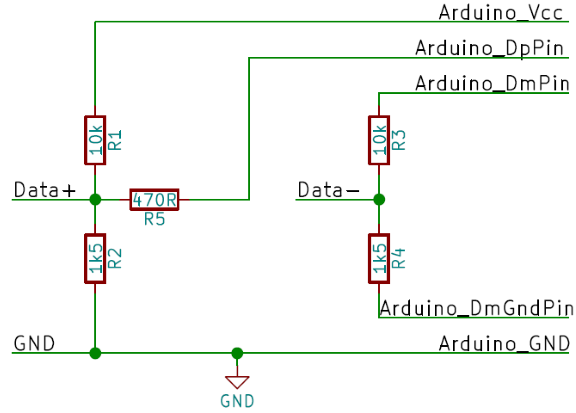
- either by slightly modifying the QC2Control circuit and "disconnecting" the bottom resistor of the D- divider when needed. In that case, the divider acts as a pull up for USB D-. I call this circuit "legacy".
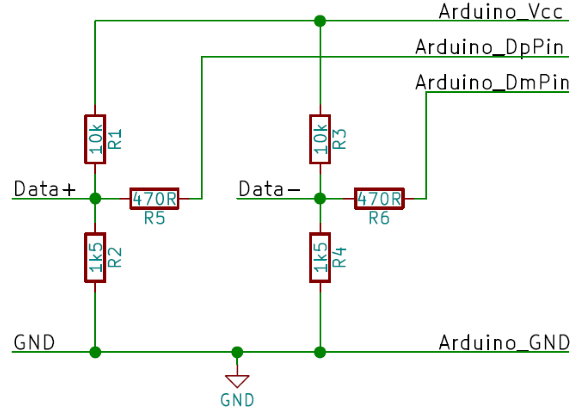
- or by using a new circuit which basically duplicates the D+ configuration to the D- side: a divider between VCC and GND plus a third resistor to the Arduino "DM" pin. In that case, outputting a HIGH level to the third resistor, a voltage of 3.3V or more can be set on USB D-. This is the recommended circuit as it does not require an additional Arduino pin.
Both circuits are supported by the library, but basically, I suggest you first try the recommended circuit, and if your QC3 charger refuses to generate anything else than 5V, then try with the legacy circuit, changing the constructor in the code accordingly.
QC3.0 class A is the most common, is mainly used for phone chargers and outputs up to 12V. It is supported by QC3Control and fully tested. Possible voltages are 5V (USB default), 9V and 12V, plus any value between 3.6V and 12V obtained by 200mV steps from 5V (or from the previous voltage reached using setMilliVoltage()).
QC3.0 class B is more targeted at laptops and can output up to 20V. WARNING: this means that the Arduino will be destroyed if powered directly from the controlled output voltage, and the use of a separate USB output, power supply or voltage regulator is mandatory. That being said, class B is now supported by QC3Control although testing was limited, and it is enabled by calling begin(true) instead of begin(). Possible voltages are then 5V (USB default), 9V, 12V and 20V, plus any value between 3.6V and 20V obtained by 200mV steps from 5V (or from the previous voltage reached using setMilliVoltage()).
As indicated above, the library supports the 2 following configurations. In all cases, all you need is a few resistors.
a) Recommended "2-wire" circuit.
b) Legacy "3-wire" circuit: Apart from the values, it is similar to the QC2Control circuit but requires a third Arduino pin instead of GND on the D- divider. Not recommended unless you have issues with the "2-wire" version
The wire color for a normal USB-cable is:
- VBUS: Red
- Data+: Green
- Data-: White
- GND: Black
You're free to pick any pin on the Arduino, just be sure to point to the right pins in QC3Control().
Arduino's Vin recommended voltage is 7-12V (absolute maximum rating 6-20V) while the voltage range supported by QC3Control (particularly in Class B) extends to 3.6-20V (compared to QC2 class A's range of 5-12V).
Depending on your required output voltage range, it may be possible to power the Arduino from the output voltage it is controlling as proposed in the QC2Control project (note though that feeding 5V to Vin is already outside of the Arduino specification). A clever use of diodes or other discrete components may work in your particular case.
Alternately, you can add a buck-boost converter which will be able to power the Arduino based on the full QC3 range, but you will probably end up with a solution generally more expensive and more complex than designing your own variable power supply in the first place.
The recommended alternative is to select a multi-port QC3 charger, to use one QC3 port as your main output and to power the Arduino's 5V pin from another (possibily non-QC) port. In that case, don't forget to connect the GND of both ports together (but NOT their VCCs of cource).
QC3Control is available via Arduino IDE Library Manager.
- Open the Arduino IDE (1.5 or above).
- In the tool-bar click Sketch -> Include Library -> Manage Libraries...
- Type in the search bar "QC3Control".
- The latest version of QC3Control should show.
- Click on it and click Install.
- Done!
Latest release: v1.4.1
- Download the latest release.
- Extract it to the
librariesfolder inside your Sketchbook. Default is[user]\Arduino\libraries. - Rename the folder to
QC3Control(remove version number). - Restart the Arduino IDE if you had it open.
- Done!
You can update to the latest version of the library in the Library Manager as well.
- Open the Arduino IDE (1.5 or above).
- In the tool-bar click Sketch -> Include Library -> Manage Libraries...
- Type in the search bar "QC3Control".
- The QC3Control library should show.
- Click on it and click Update.
- Done!
Alternatively you can download it from GitHub and simply unpack it over the current version (or remove the old version first).
Just see this simple sketch (assuming the recommended circuit is used)
#include <QC3Control.h>

//Pin 4 for Data+
//Pin 5 for Data-
//See How to connect in the documentation for more details.
QC3Control quickCharge(4, 5);

void setup() {
  //Optional
  //quickCharge.begin();

  //set voltage to 12V
  quickCharge.set12V();

  delay(1000);
}

void loop() {
  //And you can change it on the fly
  delay(1000);
  quickCharge.set9V();
  delay(1000);
  quickCharge.set5V();
  delay(1000);
  quickCharge.setMilliVoltage(6000);
  delay(1000);
  for (int i = 0; i < 10; i++) quickCharge.decrementVoltage();
  delay(1000);
  quickCharge.set12V();
}
Please note, delay() here is just used to demonstrate. Better not to stop the complete program with delay()'s.
If you can, place the call to begin() (or setMilliVoltage()) at the end of the setup(). The handshake needs a fixed time but that already starts when the QC 3.0 source (and thus the Arduino) is turned on. So by doing begin() last you can do stuff while waiting.
Note: this is just a partial overview. For full documentation, please see the next section.
[QC2 or QC3 power source] This will create a QC3Control object to control the voltage of the Quick Charge source when using the recommended "2-wire" circuit. DpPin is the pin number for the Data+ side, DmPin is the pin number for the Data- side. See How to connect?.
[QC2 or QC3 power source] This will create a QC3Control object to control the voltage of the Quick Charge 3.0 source when using the legacy "3-wire" circuit. DpPin is the pin number for the Data+ side, DmPin is the pin number for the upper resistor of the Data- side and DmGndPin is the pin number for the lower resistor of the Data- side. See How to connect?.
[QC2 or QC3 power source] Just does the handshake with a Quick Charge 3.0 (class A) source so it will accept commands for different voltages. It's not mandatory to call begin(), if it's not called before setting a voltage the library will call begin() at that moment.
[QC2 or QC3 power source] Sets the desired voltage of the QC source using discrete (QC2) mode.
[QC3 power source only] Sets the desired voltage of the QC3.0 source using continuous (QC3) mode. Setting an unreachable voltage will result in the closest supported voltage.
[QC2 or QC3 power source] Return the last voltage that was requested, or the closest one in the range 3.6 - 12V.
Important: Note that this method returns the value the library requested, not the actual voltage which may be different if the power source did not behave as exepected.
[QC3 power source only] Requests an increment or decrement of the voltage by 0.2V
Full documentation of all the methods of this library can be found inside the library located in QC3Control\doc. Just open QC3Control\doc\index.html to see all methods of QC3Control.
You can also view the documentation online via GitHub HTML Preview.
This documentation is powered by Doxygen and thus fully extracted from the source files. This README.md is also used as Main Page.
Yes you can! Just make multiple QC3Control objects connected to different pins. But be sure to connect GND of all power supplies (including QC3.0 sources) together but not the voltage rails.

