
- The System Integration project is the final project of the Udacity Self-Driving Car Engineer Nanodegree.
- Our team built ROS nodes to implement core functionality of the autonomous vehicle system, including traffic light detection, control, and waypoint following.
- This software system will be deployed on Carla (Udacity’s Self Driving Lincoln MKZ) to autonomously drive it around a test track.
Brian Erickson (UTC-8 Los Angeles)
berickson@gmail.com
https://github.com/berickson
Software Architect - Schneider Electric
Project Contributions: Team Lead, Planning Subsystem
Ryein Goddard (EST)
ryein.goddard@gmail.com ( https://github.com/goddard)
Software Engineer - Goddard Labs
Project Contributions: Classification & Traffic light detection
Thomas Bindl (UTC+1 Central Europe)
thomas.bindl@gmx.de  ( https://github.com/DTowni )
Software Engineer
Project Contributions: Control Subsystem
Yue Yang (UTC+01:00 Berlin)
yy_yangyue@hotmail.com   (https://github.com/yangyue2017)
Software Engineer
Project Contributions: Planning & Perception subsystems
R Hariharan (UTC+5.30 India)
jayhari2006@gmail.com  (https://github.com/CodeToLead)
IT Security & Compliance Delivery Manager, Ford India
Project Contributions: Integration, Testing, Performance Tuning, Documentation & Reporting.
 The above image from the Udacity course, shows the subsystems, ROS nodes and topics used in this project.
A crucial part of the vehicle’s self-driving capabilities comes from the ability to detect and classify upcoming traffic lights. This node processes images provided by the vehicle’s onboard camera and publishes upcoming traffic light information to the /traffic waypoint topic. The Waypoint Updater node uses this information to determine if/when the car should slow down to safely stop at upcoming red lights.
An Instance of TLClassifier is created during the TLDetector Class Initiatialization. Current state of Traffic light along with way points details passed as to TLClassifier TLClassfier is initialized by loading classifiers from file "./../../models/frozen_inference_graph_site.pb”. Traffic light detection takes a captured image as input and produces the bounding boxes as the output to be fed into the classification model. Saved model_sim.hdf5 file used for classification. The traffic-light classification is implemented in get_classification(self, image) function in CarND- ../ros/src/tl_detector/light_classification/tl_classifier.py.
The traffic light detection system was initially found to be always lagging 2-3 seconds behind the simulator despite improvements in prediction time and setting the queue size to one. This was due to a bug in how ROS processes large messages. The camera image subscriber was modified to have a large buffer size (52 Mb) and a queue size of one.
sub6 = rospy.Subscriber('/image_color', Image, self.image_cb, queue_size=1, buff_size=2*52428800)
The planning subsystem plans the vehicle’s path based on the vehicle’s current position and velocity along with the state of upcoming traffic lights. A list of waypoints to follow is passed on to the control subsystem.
This node was implemented by Udacity. It loads a CSV file that contains all the waypoints along the track and publishes them to the topic /base_waypoints. The CSV can easily be swapped out based on the test location (simulator vs real world).
The bulk of the path planning happens within this node. This node subscribes to three topics to get the entire list of waypoints, the vehicle’s current position, and the state of upcoming traffic lights. Once we receive the list of waypoints, we store this result and ignore any future messages as the list of waypoints won’t change. This node publishes a list of waypoints to follow - each waypoint contains a position on the map and a target velocity.
The main function of this subsystem is to modify the waypoints taken from the initial map so that the car can react to stop lights and stop in time. When this node retrieves the vehicle's pose, it finds the nearest point on the track using a k-d tree. This should perform relatively well on larger track due to the k-d tree's O(log(n)) average search speed. The final list of waypoints is published on the /final_waypoints topic. If there is a red stop light detected, this node will modify the path so that the car will stop before the light by modifying the x velocities via the waypoint.twist.linear.x of the lane message. We chose an acceleration of 2 m/s^2 which should be a relatively mild deceleration for the passenger, but still stop in a reasonable distance. Assuming uniform deceleration, we use the kinematic formula v =math.sqrt(2as) to determine stopping velocities for points a distance s from the stop light. A new waypoint is then generated using the lowest of the speed required to stop at the stop light, the original waypoint speed limit and the global speed limit. A fixed number of 100 waypoints is then published to the /final_waypoints topic
This subsystem publishes control commands for the vehicle’s steering, throttle, and brakes based on a list of waypoints to follow.
This node was given to us by Udacity. It parses the list of waypoints to follow and publishes proposed linear and angular velocities to the /twist_cmd topic
The DBW node is the final step in the self driving vehicle’s system. At this point we have a target linear and angular velocity and must adjust the vehicle’s controls accordingly. In this project we control 3 things: throttle, steering, brakes. As such, we have 3 distinct controllers to interface with the vehicle.
We used the provided PID controller to calculate the acceleration. The upper output boundary is set to 1.0. The lower output boundary is given by the deceleration limit of -5.0. As input we used the crosstrack error calculated by subtracting the current velocity from the proposed velocity and time interval dt. This interval is given by 1/rospy.Rate. As mentioned, this value shouldn’t set less than 10hz, otherwise Carla will return control to the driver.
Throttle is set to the positive acceleration values provided by the PID controller. If acceleration is less than zero, throttle is set to zero.
Steering values are calculated by the provided yaw controller. This controller depends on the wheel base, the steer ratio, the maximum lateral acceleration and the maximum steer angle.
If the output of the PID controller is less than zero, its called deceleration. To convert deceleration into torque, we used the following equation: torque = deceleration * (self.vehicle_mass + self.fuel_capacity * GAS_DENSITY) * self.wheel_radius Additionally if deceleration is less than brake deadband, the brake is set to sero.
We implemented a guard to stop the car if the proposed velocity is less than 1 km/h. We also tuned the kp parameter of the PID controller to 0.65. As it turned out the velocity is rather stable and the acceleration is still high enough to accelerate the car properly.
Initial of the testing was done within the Udacity supplied simulator.
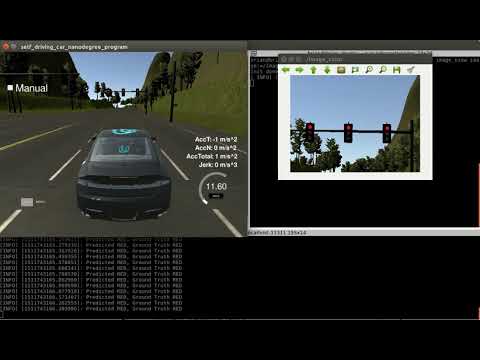
Traffic light classification was done using image collections
Testing was done on Udacity site collected data using rosbags. For example:
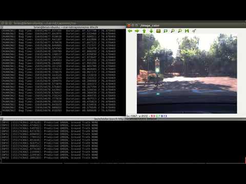
Run our software:
roslaunch launch/site.launch
Play supplied bag
rosbag play -l loop_with_traffic_light.bag
View images
rosrun image_view image_view image:=/image_raw