Shamelessly forked from Juan Chong. I took his original Arduino library code and modified it to work with the ADIS16488 IMU. This is a work-in-progress which may eventually be turned into a proper Arduino library. We are also working on a corresponding ROS node.
TODOs:
- Add all register definitions and automatic page switching
- Improve communication protocol
- Convert this into a proper Arduino library with examples etc.
Messages from the Teensy consist of a 4-byte header 0x41 0x42 0x43 0x44,
followed by the size of the payload, the payload itself, a 1-byte CRC
and a 0x51 0x52 0x53 0x54 trailing sequence.
For a precise definition of the payload structure, see ADIS16488_regtest.ino#L89.
CRC algorithm is defined in crc.h
| Byte no. | Type | Description |
|---|---|---|
| Header start | ||
| 0 | byte | 0x41 |
| 1 | byte | 0x42 |
| 2 | byte | 0x43 |
| 3 | byte | 0x44 |
| 4 | byte | Size of message from Counter to Temperature (inclusive) |
| Payload start | ||
| 5:8 | uint32_t | Counter - increments in each new message |
| 9:12 | float | Gyro rate X |
| 13:16 | float | Gyro rate Y |
| 17:20 | float | Gyro rate Z |
| 21:24 | float | Integrated gyro angle X |
| 25:28 | float | Integrated gyro angle Y |
| 29:32 | float | Integrated gyro angle Z |
| 33:36 | float | Acceleration X |
| 37:40 | float | Acceleration Y |
| 41:44 | float | Acceleration Z |
| 45:48 | float | Magnetometer X |
| 49:52 | float | Magnetometer Y |
| 53:56 | float | Magnetometer Z |
| 57:60 | float | Barometric pressure |
| 61:64 | float | Device temperature |
| Payload end | ||
| 65 | uint8_t | CRC |
| Trailing sequence | ||
| 66 | byte | 0x51 |
| 67 | byte | 0x52 |
| 68 | byte | 0x53 |
| 69 | byte | 0x54 |
Teensy currently accepts three commands. They consist of three bytes:
0x32 0x57 <command>, where the command can be one of the :
0x8B: Start the gyro bias auto null command. IMU estimates the gyro bias and stores it in its internal compensation registers. Takes >2000ms to complete.0x8C: Software reset the IMU. Afterwards, the IMU is re-configured to the proper settings used in this sketch. Takes 250ms to complete.0x8D: Reset the integrated gyro angles.
Below is the original README:
An example C++ library and Teensyduino project for the ADIS16488 iSensor Ten Degrees of Freedom Inertial Sensor
This example library was written to give engineers, students, and makers a starting point for using a high-performance, compact, precision inertial sensor. The code in this repository will provide the user with:
- A header file listing all of the unit's available registers
- Functions for reading output registers and writing control registers using 8-bit frames
- Note that the ADIS16448 requires 16 bit SPI transactions. spi.transfer() is called twice for each transfer and CS is manually toggled to overcome the Arduino language's limitation
- Functions for performing common routines such as resetting the sensor
- Burst-mode data acquisition and checksum verification
- Example Arduino sketches which synchronously read data from the sensor and write it to the serial port
- In order to compile and execute the Teensyduino sketch, you'll need to download the Arduino package (v1.6.11 as of this writing). You can download the IDE here.
- You'll also need to install the Teensyduino library provided by PJRC.
- Finally, you'll need a Teensy sold by PJRC here. Version 3.x or LC is supported.
- The main Teensyduino sketch issues a command to clear the terminal window after displaying data. For best results, connect to your Teensy using PuTTY, an open source terminal program.
Once you've installed the Arduino IDE and Teensyduino libraries, copy the ADIS16448 folder into My Documents > Arduino > libraries
Be sure to restart the Arduino IDE to refresh the library directory!
If using a Teensy, the onboard regulator should provide enough current for the ADIS16448 to properly operate.
You'll need to build a cable to interface the sensor with the ADIS16448/PCBZ. The image below shows a custom Teensy interface board for iSensors products.

Pin assignments for the Teensy can be found in the example sketch comments.
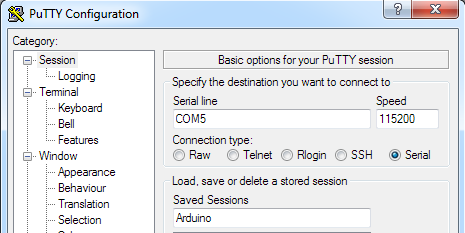
Once you have the sensor connected and have opened the ADIS16448_Teensy_BurstRead_Example.ino example sketch, use PuTTY to connect to the arduino using the following settings. Note that your COM port may be different:
If everything is working, you should see a screen like this:

The demo software will only update the screen ~2 times/second, but every sample is being captured by the interrupt service routine.
A single burst frame should look like this when viewed with a logic analyzer:
