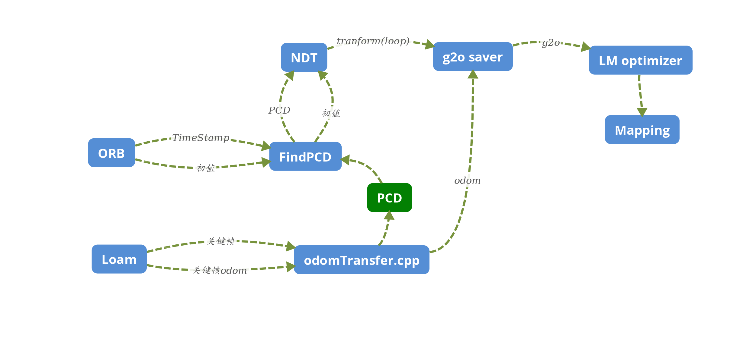
This program use ROS and it is divided into 2 different part. The 1st part is to get the g2o file from the Lidar odometry and get the loop closure data from orb.
The second part is to get the loop closure information and calculate the transform by NDT(normal distribution transform) to get the accurate loop closure information to the first part.
The ROS requirement is Kinetic and it depends on Eigen 3 PCL 1.5+ Cholmod G2O
Here is how to run it :
cd catkin_ws
catkin_make
rosrun g2oodomsave g2oSaver
rosrun g2oodomsave ndtCalc
I added a new tools to switch the coordinate of LOAM to the rslidar coordinate, and this program is called OdomTransfer. It subscribe the odom and point topic to fix the odom problem.
It will publish the point and odom after transform.
The main function is to get the odom and the loop closure edge of the LOAM and ORB.
subscribe<nav_msgs::Odometry>("/after_rotate",1000, &G2oSaver::lidarOdomHandler,this);
subscribe<nav_msgs::Odometry>("/ndt_loop_tf",1000, &G2oSaver::ndtTrans,this); This read the topic named /ndt_loop_tf from ndtTransCalc and the message type is nav_msgs::Odometry .
It also read the after_rotate from Odomtransfer to get the correct odometry.
We assume the **loopClosure->twist.covariance.elems[0] ** as the information which tells this odom message is previous (set it as 1) or this is the current frame(set as 0).
We also assume the loopClosure->twist.covariance.elems[1] as the loop closure ID of the Key Frame. For example we find the loop closure at frame 40 and 104, we set the loopClosure->twist.covariance.elems[1] equals 40 as the previous frame and 104 for the current frame.
The transform is the result after NDT, need to be deal with later. Seen in 2.
Here are the steps that how to calculate two steps:
- Calculate the origin position of two cloud according to the Lidar Odometry.
- Calculate the relative transform between two frame( this is for relative transform in a map, we can regard it as the registering for the wall and trees).
- This transform in step 2 is the loop closure edge's transform.
- Because of the point cloud and the odometry is different with the Lidar Mapping, we can not get the point by odometry but we just need to rotation of the point cloud and save it.
- Calculate the relative transform between two frame( this is for relative transform in a map, we can regard it as the registering for the wall and trees).
- This transform in step 2 is the loop closure edge's transform.
loopClosure->header.stamp.nsec and loopClosure->header.stamp.sec are the time stamp of these two frame.
- Later we may calculate the real transform from here with the odom.
- Air pressure interface to be finished.
- Bug fixed : without initial vertex
- Use the 1HZ odom for demo.
This part is currently being changing, and it may change into the Ceres library in the future
subscribe<std_msgs::Bool>("/g2o_finish",1000, &LMoptimizer::lmStart,this);
advertise<std_msgs::Bool>("/mapping",5); When it get true from Ros message from g2oSaver it will run a optimize int the relative .g2o file.
It will also advertise mapping to the **mapping ** node to formulate the point cloud map.
- Finish.
The mainly goal is to get two point cloud and calculate the trans between two frame and give the transform between two robot pose. Here are the test that without a correct initial pose of two point cloud, and these two point clouds' transform is given by the LOAM.
This program have 3 topics to subscribe from PCDFinder.
subscribe<nav_msgs::Odometry>("/loop_coarse_tf",2, &ndtcalc::picNumHandler, this);
subscribe<sensor_msgs::PointCloud2>("/ndt_points_past",2, &ndtcalc::pointCloudHandler, this);
subscribe<sensor_msgs::PointCloud2>("/ndt_points_cur",2, &ndtcalc::pointCloudHandler, this);
/loop_coarse_tfis the relative transform which is from the previous frame to current frame. This also tells the number connected with two Vertex form find PCD node/ndt_points_pastis the previous loop point cloud form find PCD node ./ndt_points_curis the current loop closure point cloud form find PCD node .
- Odom transfer not solved
- Ros connector finish
- Test the whether the TF is correct
- Current it will read two test PCD, later remove it.
This program transform the odom and the point cloud form the LOAM, there are 4 publishers after_rotate pc_after_rotate after_rotate_01hz pc_after_rotate_01hz and the after_rotateis the odometry which is correct to the robosense Lidar odom, this odom is from the 1hz odom.
-
Finish
-
Tested
This program is mainly to find the loop closure Point Cloud in the Hard disc and this action is based on the time stamp from the ORB.
advertise<nav_msgs::Odometry>("/loop_coarse_tf", 2);
advertise<sensor_msgs::PointCloud2>("/ndt_points_past", 2);
advertise<sensor_msgs::PointCloud2>("/ndt_points_cur", 2); The loop_coarse_tf is the initial value for NDT but if we do not have this value it seems also works fine. This value is given by the ORB.
The ndt_points_past ndt_points_cur are results after find the PCD in the Hard disc which given to NDT for calculate. The path is args="$(find g2oodomsave)/pcd_buffer/" in the launch file.
the major part the in the PrecedentCallback function. After receiving /loop_info_current and /loop_info_precedent, the node save the
The mapping node is to get the g2o file and add these program to one file. The result will publish to the rviz for demonstrate. This node read 2 g2o file and calculate the differ between two position and give this result to the point cloud and get the result.
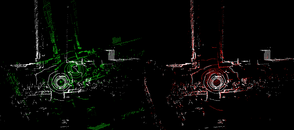
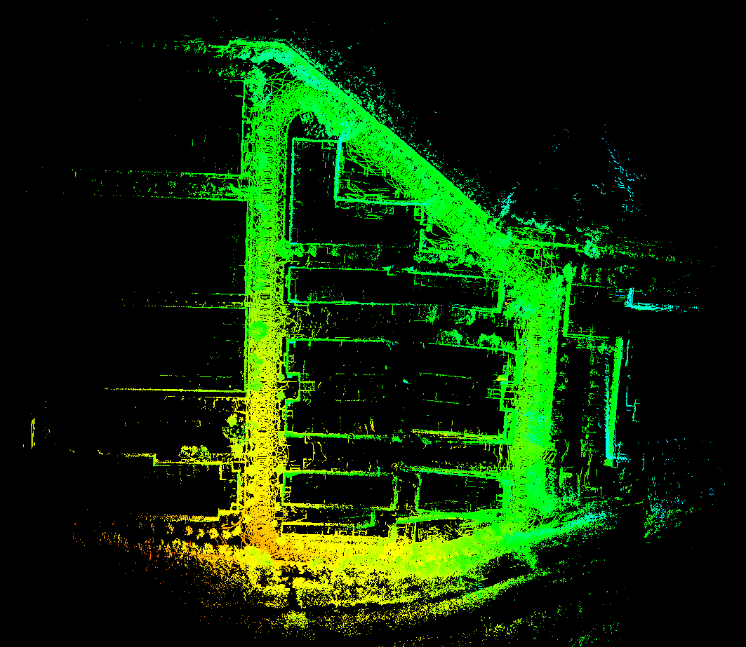
Here is the 1 loop-closure edge test for the Suteng Industry area:
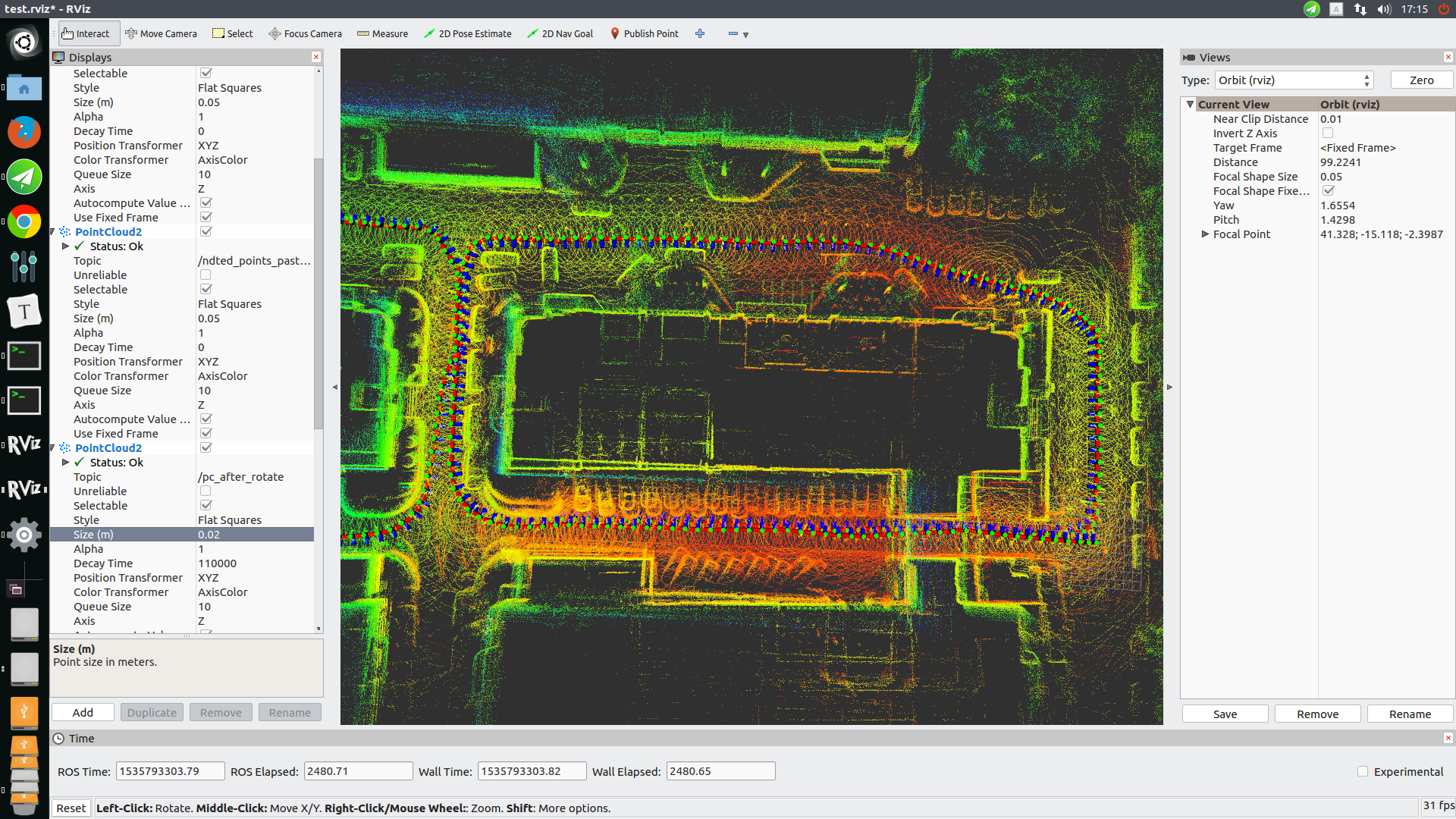
After add the loop closure edge:
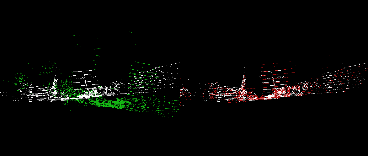
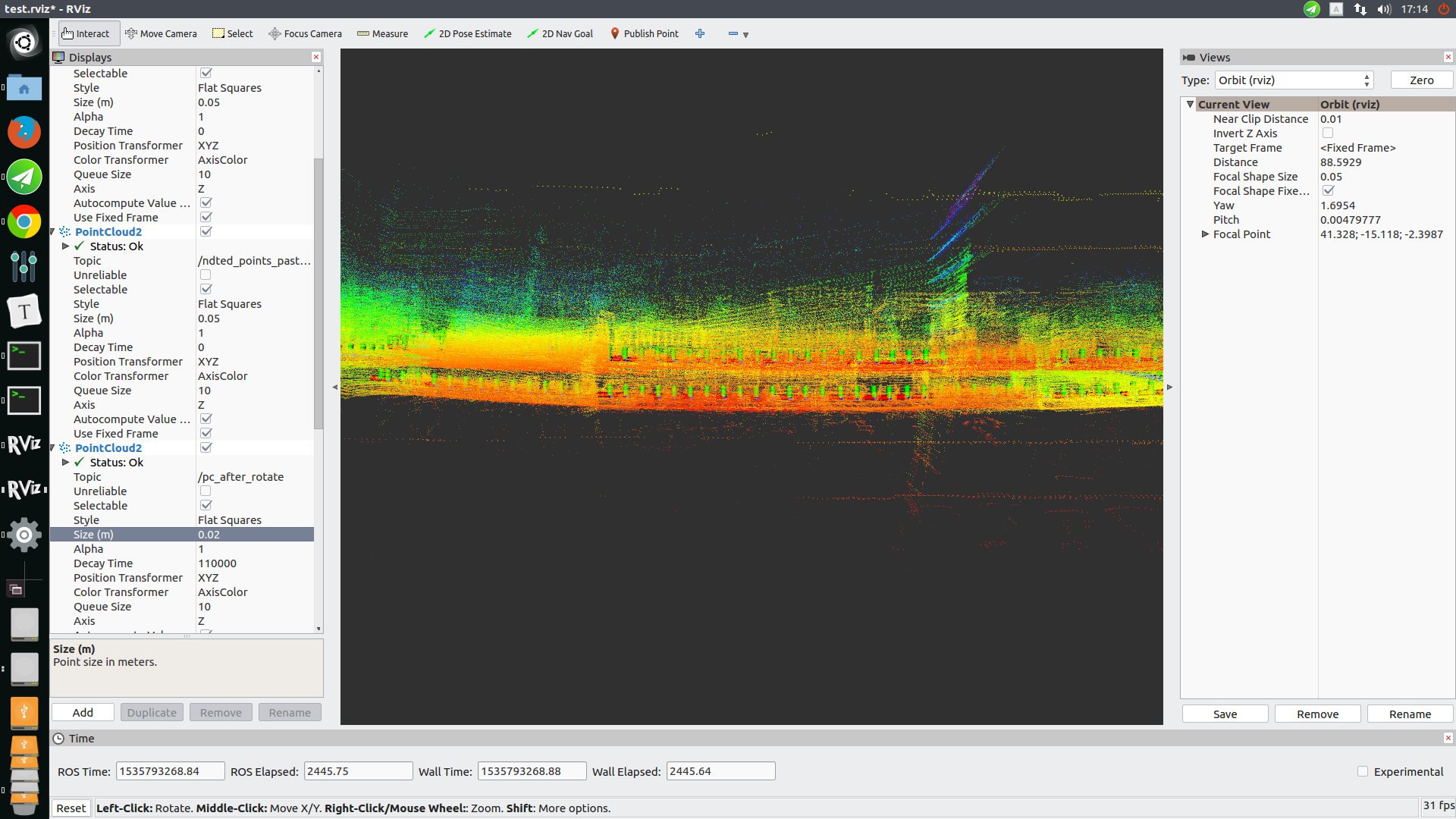
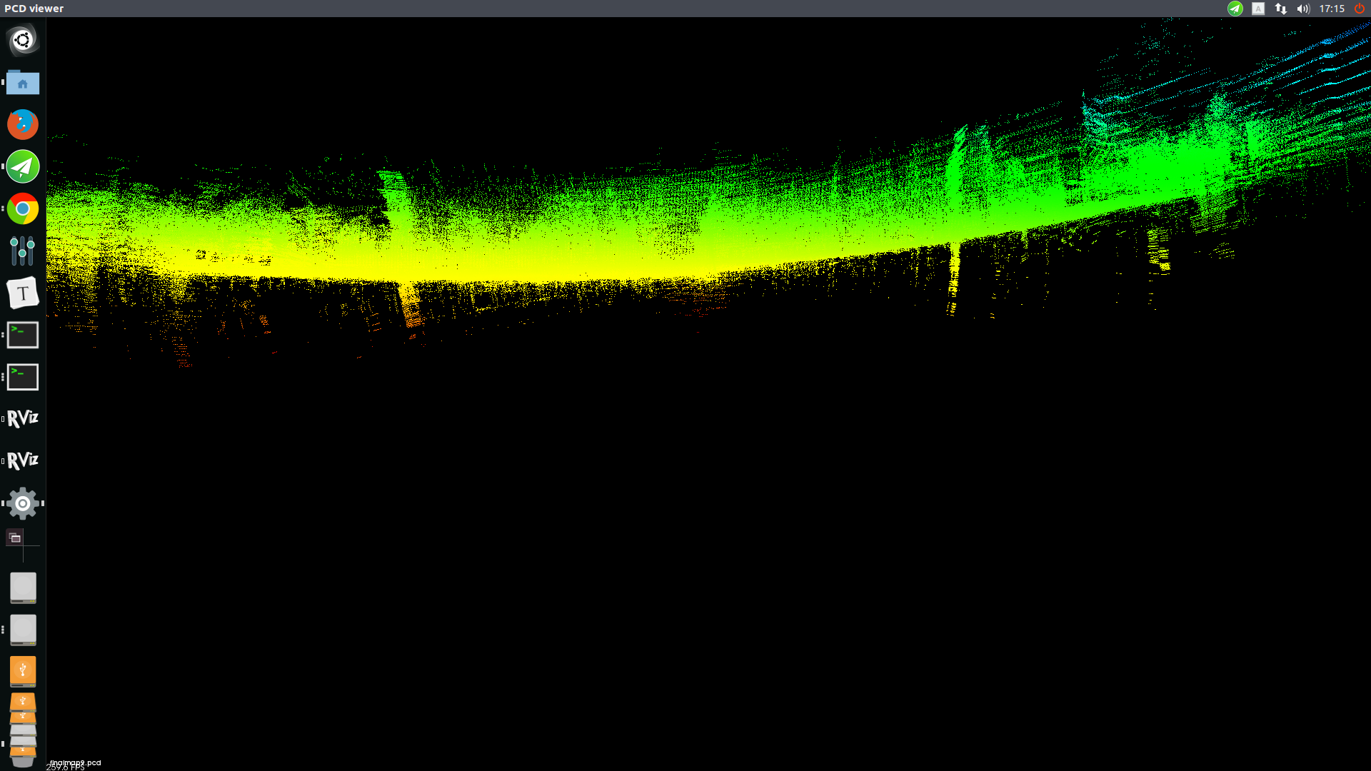
Here is the result from the LOAM and the top view and the side view is below:
This is the side view of the loam and we can see the two layers of the ground
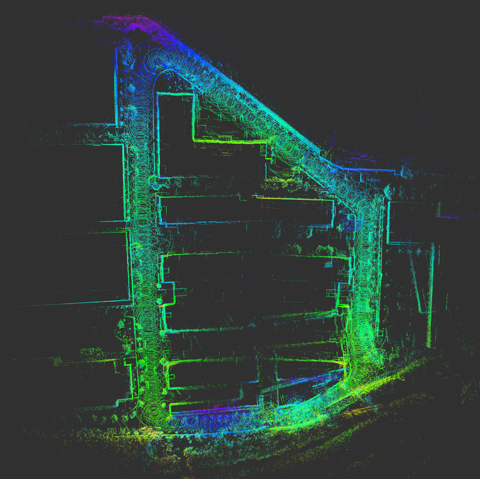
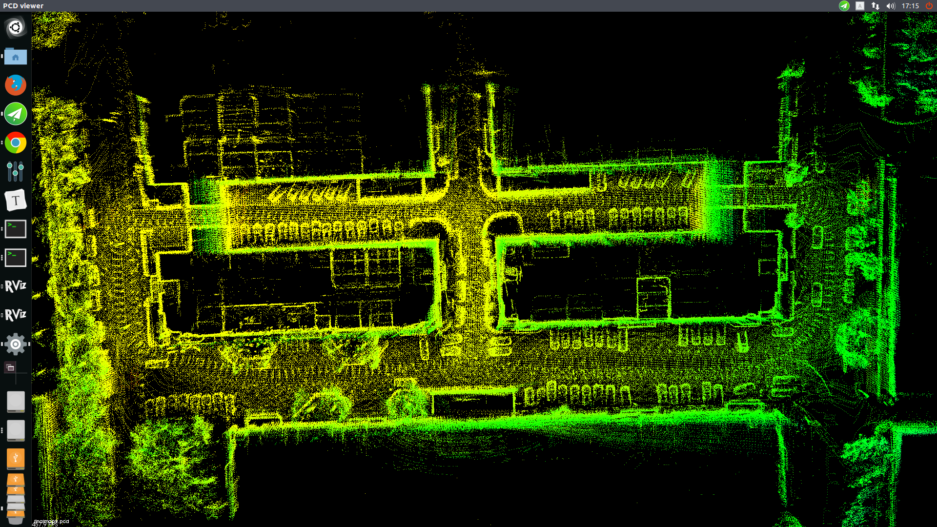
Here is the result of the loop closure and the result is:
Current this program mainly use the G2O version in this folder, if it use other edition G2O it will have several problem:
  		1. *Segment*Fault when loading edges.
  		2. Wrong Information matrix when save it as g2o file.
- Change the NDT to geit the ROS message
- Test more loop closure edges
