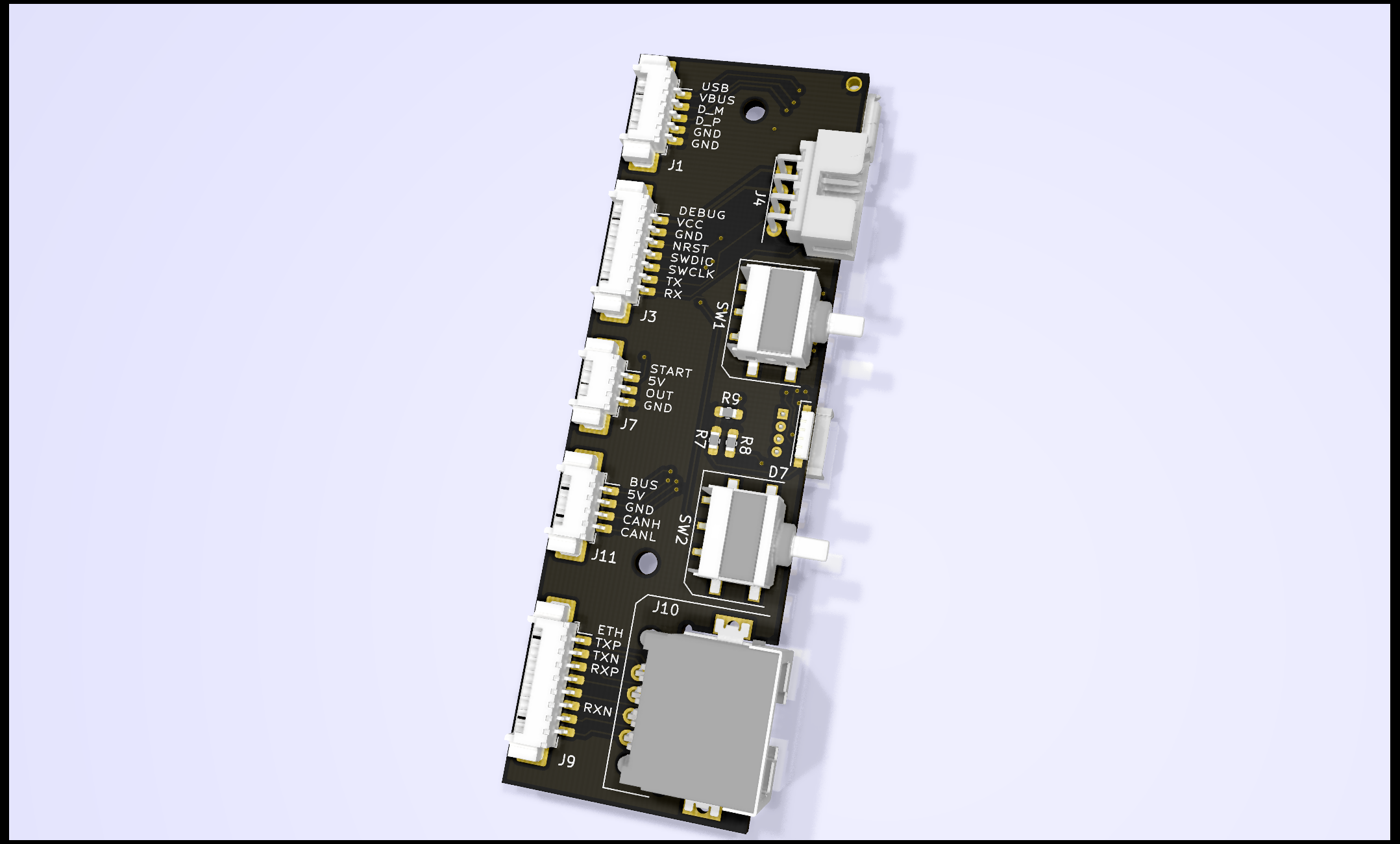
This small PCB is used to expose debug and HMI signals from inside the robot to the external world through a front panel. The main goal is to simplify the wiring and have a sturdy mount.
- USB Forwarding: Picoblade -> USB
- Ethernet forwarding: Picoblade -> RJ45
- CVRA debug forwarding
- CAN forwardig
- 6 LEDS + Team selection indication (RGB)
- 2 buttons for team selection
- Connector for the hall sensor starter: 5V, Signal, GND
- One connector to the nucleo shield for all GPIOs
- Max width: 80 mm, but lower is better
- Max length: 30mm
- Connectors must be at least 1.5mm off the board to go through the panel
- The board height should be as symmetrical as possible
- 2xM2 mounting holes.
- SWDIO exposed through something sturdier than Picoblade used in the past
- The silkscreen should document pinout to simplify troubleshooting

