Overview
The goals / steps of this project are the following:
- Compute the camera calibration matrix and distortion coefficients given a set of chessboard images.
- Apply a distortion correction to raw images.
- Use color transforms, gradients, etc., to create a thresholded binary image.
- Apply a perspective transform to rectify binary image ("birds-eye view").
- Detect lane pixels and fit to find the lane boundary.
- Determine the curvature of the lane and vehicle position with respect to center.
- Warp the detected lane boundaries back onto the original image.
- Output visual display of the lane boundaries and numerical estimation of lane curvature and vehicle position.
The following Jupyter notebook contains the solution .
The code for this step is contained in the first code cell of the Jupyter notebook located in "./solution.ipynb".
I start by preparing "object points", which will be the (x, y, z) coordinates of the chessboard corners in the world. Here I am assuming the chessboard is fixed on the (x, y) plane at z=0, such that the object points are the same for each calibration image. Thus, objp is just a replicated array of coordinates, and objpoints will be appended with a copy of it every time I successfully detect all chessboard corners in a test image. imgpoints will be appended with the (x, y) pixel position of each of the corners in the image plane with each successful chessboard detection.
I then used the output objpoints and imgpoints to compute the camera calibration and distortion coefficients using the cv2.calibrateCamera() function. I applied this distortion correction to the test image using the cv2.undistort() function and obtained this result:
Here is an example test image corrected after applying the undistortImage() function defined in the second cell of the :
I created an RGB2HLS() function for the color transform in the fourth cell of the . The function Convert the input image from RGB colorspace to HLS colorsapce. It returns all three channels as three images. Here is an example output for this step.
Afterewards, I created a binarizeImage() function in the fifth cell of the . It takes as input a single channel image, orientation parameter, threshold minimum and maxim value, and the kernal size. It applies a Sobel derivative according to the orientation parameter followed by scaling [0,1]. Finally, the image is binarized according to the minimum and maximum threshold values. Here is a sample output of this function:
Then, I created a thresholdImage() function also in the fifth cell of of the . It takes as an argument, HLS channel images, minimum/maximum binary/color threholds, and the kernal size. It calculates the Sobel x-derivative of the L-channel and binarize it. Afterwards, it threshold the S-channel. The function returns two images, a pseudo color image, and the combined binarize image. Here is a sample output of this function:
The code for my perspective transform includes a function called imageTransform(), which appears in the sixth cell of the . The function takes as input a single-channel image. It defines a ROI and apply perspective transform to wrap an image (birds eye-view). Here is an example output of the transform:
I defined a histogram() function to initialize the location of left and right lane. The function is defined at the start of the seventh cell of the . Here is an example output of the function on the test image:
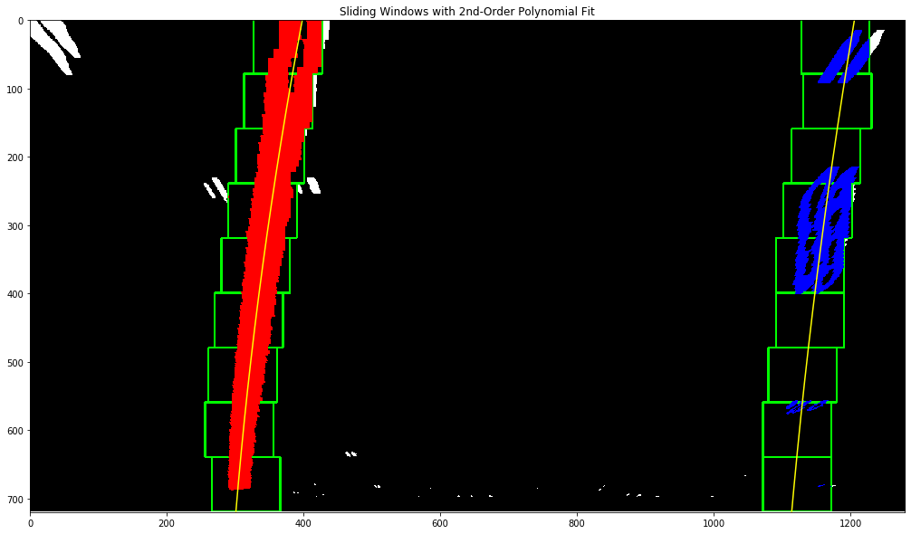
Then I created a slidingWindow() also on the seventh cell of the . The function detects the land boundaries, afterwards, apply a second order poly-nomial fit to find curve lines.
Here is an example output of the function on the test image:
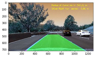
The code to determine road curvature and vehicle offset from the center is defined by function called calculateROC(), which appears in the eigth cell of the . The function takes as input a warped image and the left and right lane polynomial. It calculates the average ROC and the offset from the middle bottom.
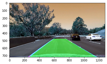
The code to display to unwarp the results back to road is defined inside drawLineBoundaries() function, which appears on the ninth cell of the . The function takes as input the undistorted image, Warped image, left/right lanes polynomials. It unwarp the image and draw line boundries on the undistorted image. Here is an example of my result on a test image:
Here is an example of the final annotated image:
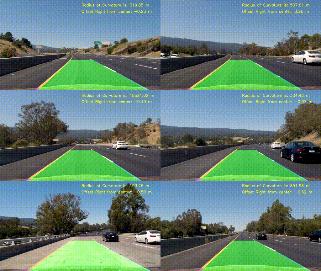
1. Here's a link to my video result
The project uses image processing and computer vision techniques to find road lanes, road curvature and the vehicle position offset. Ofcourse, it's cann't be generalized out of the box for real lane following under all conditions.
The pipeline is sensitive to the enviorment conditions such as changing light conditions and shadows. Various parameters such as used for the binirization process are also citical to the system output. The lack of tunning metric also makes it harder to tune. One relies on the visual output of the algorithm. The combinations of various channels inside thresholdImage() is also very tricky.
The process may fail during snow and during rain conditions. In order to improve the execution performance of the pipeline, it can be implemented in C/C++.
For future work, various other colorspaces may also be tried.
Correct determination of the src and dst points inside the imageTransform() are also critical.
In case of incoming traffic the solution might fail, in such condition, object detection might help.


